11
Test Procedures
TROUBLESHOOTING AND ELECTRICAL
SYSTEM: GASOLINE VEHICLES
2085
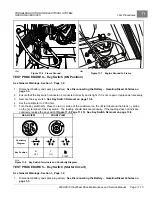
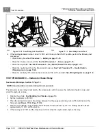
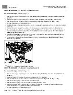
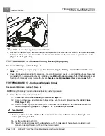
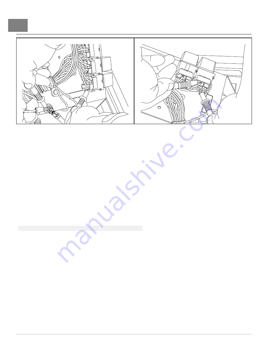
Figure 11-10
Start Relay Coil Circuit Test
2086
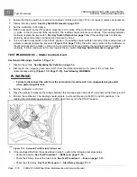
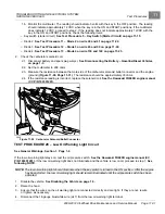
Figure 11-11
Start Relay Contact Test
8.
If the reading obtained in step 5 is not 12 VDC with the key in the START position, perform the following test
procedures:
– Check battery.
See Test Procedure 1 – Battery on page 11-10.
– Check the 10-amp fuse (on w109).
See Test Procedure 2 – Fuse on page 11-13.
– Check the key switch.
See Test Procedure 5 – Key Switch (Starter Circuit) on page 11-15.
– Check the neutral switch on the transmission housing.
See Test Procedure 15 – Neutral Switch
– Check for continuity of the wire harness on wires w138, w110, and w43.
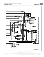
See Wiring Diagram on page 11-8.
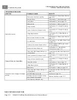
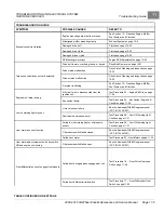
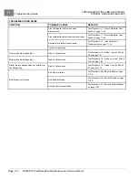
TEST PROCEDURE 8 – Carburetor Heater Relay
See General Warnings, Section 1, Page 1-2.
NOTE:
Keep the battery connected during this test procedure.
The carburetor heater relay is activated by the oil pressure switch to ensure the carburetor heater is only used
while the engine is running.
1.
Disable the vehicle.
See Disabling the Vehicle on page 1-3.
2.
Set the multimeter to 20 VDC.
3.
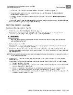
Place the probes to measure the voltage between the 18-gauge purple relay wire (w135) terminal and the
frame ground
.
4.
Monitor the multimeter. The reading should indicate 0 volts with the key off. The reading should indicate
approximately 12 VDC with the key on.
5.
If the reading is 12 VDC and the relay does not click when the engine starts, replace the relay.
Page 11-18
2008-2012 All-Wheel Drive Maintenance and Service Manual
Summary of Contents for Carryall 295 SE
Page 2: ......
Page 20: ......
Page 28: ......
Page 58: ......
Page 66: ......
Page 100: ......
Page 122: ......
Page 150: ......
Page 157: ......
Page 190: ......
Page 197: ......
Page 236: ......
Page 284: ......
Page 386: ......
Page 394: ......
Page 442: ......
Page 452: ......
Page 454: ......
Page 455: ......
Page 456: ......

