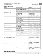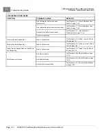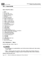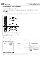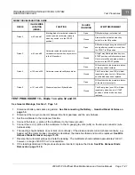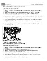
TROUBLESHOOTING AND ELECTRICAL SYSTEM:
GASOLINE VEHICLES
Test Procedures
11
2087
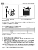
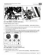
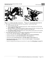
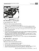
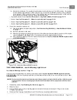
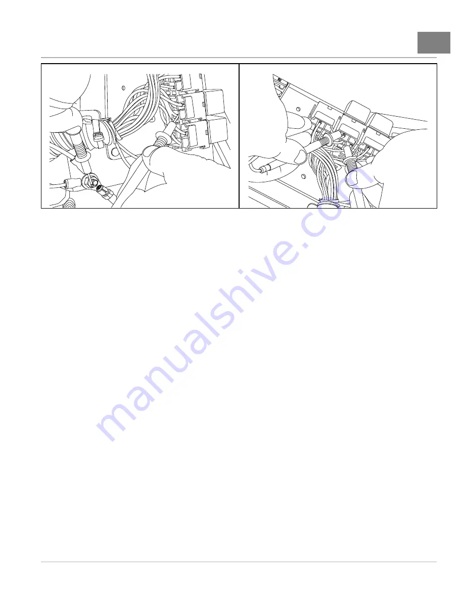
Figure 11-12
Carburetor Heater Relay Coil Circuit Test
2088
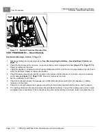
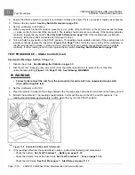
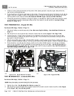
Figure 11-13
Carburetor Heater Relay Contact Test
6.
If the reading is 12 VDC and the relay clicks when the engine starts, check the relay contacts.
6.1. Set the multimeter to 200 ohms.
6.2. Check for continuity between the 18-gauge gray wire (w111) and the 16-gauge green wire (w114) relay
terminals
6.3. Monitor the multimeter. The multimeter should NOT indicate continuity with the key in the ON position and
the engine off. The multimeter should indicate continuity when the engine starts.
6.4. If the multimeter indicates continuity while the key is in the ON position and the engine is off, the contacts
have failed closed. Replace the relay.
7.
If the reading obtained in step 5 is not 12 VDC when the engine starts, perform the following test procedures:
– Check the battery.
See Test Procedure 1 – Battery on page 11-10.
– Check the oil pressure switch.
See the Kawasaki FH680D engine manual (CC P/N 103351201).
– Check the 10-amp fuse (on w109).
See Test Procedure 2 – Fuse on page 11-13.
– Check the key switch.
See Test Procedure 5 – Key Switch (Starter Circuit) on page 11-15.
– Check the neutral switch on the transmission housing.
See Test Procedure 15 – Neutral Switch
– Check for continuity of the wire harness on wires w139, w135, and w47.
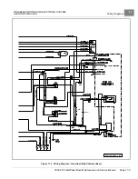
See Wiring Diagram on page 11-8.
2008-2012 All-Wheel Drive Maintenance and Service Manual
Page 11-19
Summary of Contents for Carryall 295 SE
Page 2: ......
Page 20: ......
Page 28: ......
Page 58: ......
Page 66: ......
Page 100: ......
Page 122: ......
Page 150: ......
Page 157: ......
Page 190: ......
Page 197: ......
Page 236: ......
Page 284: ......
Page 386: ......
Page 394: ......
Page 442: ......
Page 452: ......
Page 454: ......
Page 455: ......
Page 456: ......

