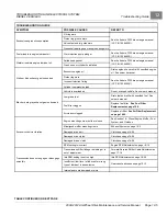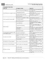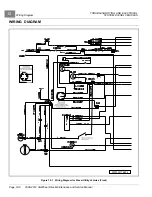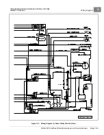
TROUBLESHOOTING AND ELECTRICAL SYSTEM:
DIESEL VEHICLES
Test Procedures
12
Load Test
NOTE:
Ensure that the battery is fully charged before performing the following test procedure.
1.
Disable the vehicle.
See Disabling the Vehicle on page 1-3.
2.
Check for loose or corroded battery terminal connections. Clean, tighten and replace connections as necessary.
3.
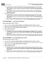
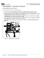
Connect a 160-ampere load tester to the battery posts.
See following NOTE.
NOTE:
If a load tester is not available, a load can be placed on the battery by removing the fuel shut-off solenoid
wires and activating the starter motor. If this method is used, the voltage must be read when the starter
motor is turning.
See following CAUTION.
CAUTION
• Activating the starter for more than a few seconds could result in damage to the starter motor, the
starter, and/or the flywheel gears.
4.
Turn the load tester switch to the ON position.
5.
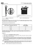
Read the battery voltage after the load tester has been turned ON for 15 seconds. The minimum acceptable
battery voltage for proper engine starting is approximately 9.6 VDC.
6.
If the battery voltage is acceptable, or if the electrical problem continues after the battery has been replaced,
test the electrical circuits.
7.
If the voltage reading exceeds 9.6 volts at 70 °F (21 °C) (electrolyte temperature), check the starter.
See the
Kubota D722 diesel engine manual (CC P/N 103840201). See also the following NOTE.
NOTE:
Record the voltage reading at 70 °F (21 °C). At lower electrolyte temperatures, the voltage reading will be lower.
8.
If the reading is less than 9.6 volts at 70 °F (21 °C) (electrolyte temperature), check the battery electrolyte
in each cell.
TEST PROCEDURE 2 – Fuse
See General Warnings, Section 1, Page 1-2.
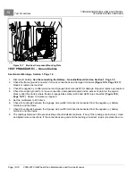
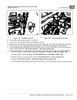
The fuse block is located on the electrical component mounting plate
1.
Disconnect battery.
See Disconnecting the Battery – Gasoline/Diesel Vehicles, Section 1, Page 1-3.
2.
Remove the electrical component cover.
3.
Ensure the wires are connected correctly and are tight. If they are not, rewire or tighten as necessary.
4.
Remove the fuse to be tested from the fuse block.
5.
Connect the probes of a multimeter set to 200 ohms to the fuse terminals. The reading should be continuity. If
there is no continuity, determine and repair the cause of the fuse failure. Replace the fuse with a properly
rated new one.
See following WARNING.
WARNING
• If a fuse is blown, determine the cause of the failure and make necessary repairs before installing a
new fuse. Use the appropriately rated fuse; if a fuse with a higher amp rating is used, damage to the
vehicle electrical system may occur.
2008-2012 All-Wheel Drive Maintenance and Service Manual
Page 12-15
Summary of Contents for Carryall 295 SE
Page 2: ......
Page 20: ......
Page 28: ......
Page 58: ......
Page 66: ......
Page 100: ......
Page 122: ......
Page 150: ......
Page 157: ......
Page 190: ......
Page 197: ......
Page 236: ......
Page 284: ......
Page 386: ......
Page 394: ......
Page 442: ......
Page 452: ......
Page 454: ......
Page 455: ......
Page 456: ......

