TROUBLESHOOTING AND ELECTRICAL SYSTEM:
DIESEL VEHICLES
Test Procedures
12
– Check the 30-amp fuse (on w125).
See Test Procedure 2 – Fuse on page 12-15.
– Check the key switch.
See Test Procedure 4 – Key Switch (Starter Circuit) on page 12-17.
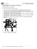
– Check the neutral switch on the transmission housing.
See Test Procedure 17 – Neutral Switch
– Check for continuity of the wire harness on wires w141, w138, w110, and w125.
TEST PROCEDURE 9 – Fan Relay
See General Warnings, Section 1, Page 1-2.
The fan relay activates the radiator fan when the engine coolant reaches a temperature range of 187 °F to 198 °F
(86 °C to 92 °C) and closes the fan thermostat switch.
1.
Disable the vehicle.
See Disabling the Vehicle on page 1-3.
2.
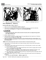
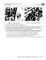
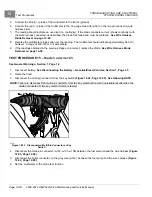
Disconnect the 16-gauge green wire (w127) from the starter solenoid coil to prevent the vehicle from
unintentionally starting
.
See following WARNING.
WARNING
• Failure to disconnect the wire from the solenoid coil could result in an unexpected engine start
when performing this test.
3.
Check power to the relay.
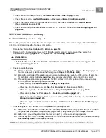
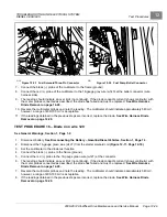
3.1. Set the multimeter to 20 VDC and place the probes to measure the voltage between the 18-gauge yellow
fan relay wire (w146) terminal and the frame ground
.
3.2. Monitor the multimeter. The reading should indicate 0 volts with the key in the OFF position. If not, check
for a short or incorrect wiring between the yellow fan relay wire (w146) terminal and the key switch.
3.3. The reading should indicate approximately 12 VDC with key in the ON position. If so, proceed to step
4. If not, perform the following test procedures:
– Check battery.
See Test Procedure 1 – Battery on page 12-12.
– Check the 30-amp fuse (on w125).
See Test Procedure 2 – Fuse on page 12-15.
– Check the key switch.
See Test Procedure 5 – Key Switch (ON Position) on page 12-18.
– Check diode 2.
See Test Procedure 14 – Diode 2 on wire 40 on page 12-27.
– Check for continuity of the wire harness on wires w114, w146, w121, w48, w37, w24, and w125.
– Check the engine coolant thermostat switch.
See Test Procedure 10 – Thermostat Switch on page
4.
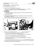
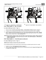
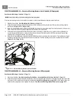
If the reading is 12 VDC with key in the ON position, check relay function.
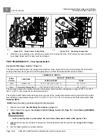
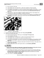
4.1. At the relay, place the meter probes to check continuity between the 14-gauge yellow wire (w107) and the
14-gauge blue wire (w145) relay terminals
when the relay is activated.
4.2. At the relay, ground the yellow/black fan relay wire (w114) to the frame with a jumper wire.
4.3. Turn the key switch ON. The relay should click, the fan should run and the meter should indicate continuity.
See following NOTE.
If not, replace the relay.
NOTE:
The start and accessory relays may be removed temporarily to isolate the sound of the fan relay click.
2008-2012 All-Wheel Drive Maintenance and Service Manual
Page 12-21
Summary of Contents for Carryall 295 SE
Page 2: ......
Page 20: ......
Page 28: ......
Page 58: ......
Page 66: ......
Page 100: ......
Page 122: ......
Page 150: ......
Page 157: ......
Page 190: ......
Page 197: ......
Page 236: ......
Page 284: ......
Page 386: ......
Page 394: ......
Page 442: ......
Page 452: ......
Page 454: ......
Page 455: ......
Page 456: ......


