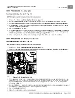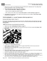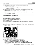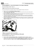
TROUBLESHOOTING AND ELECTRICAL SYSTEM:
DIESEL VEHICLES
Test Procedures
12
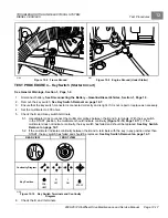
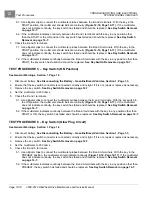
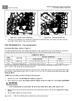
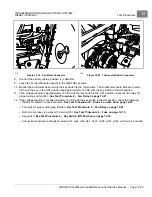
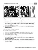
4.1. Set a multimeter to 200 ohms.
4.2. Use an alligator clip to connect the black (–) probe of the multimeter to the frame (ground).
4.3. Use an alligator clip to connect the red (+) probe of the multimeter to the white wire terminal.
4.4. The multimeter should indicate an over limit (no continuity) at room temperature. If the multimeter indicates
continuity at room temperature, replace the thermostat switch.
See Thermostat Switch Removal on
4.5. Leave the black (–) probe of the multimeter connected to the frame (ground). Use an alligator clip to
connect the red (+) probe of the multimeter to the black wire terminal.
4.6. The multimeter should indicate an over limit (no continuity) at room temperature. If the multimeter indicates
continuity at room temperature, replace the thermostat switch.
See Thermostat Switch Removal on
G
N
I
N
R
A
W
Y
R
U
J
N
I
E
R
E
V
E
S
E
S
U
A
C
N
A
C
T
O
H
d
l
o
f
i
n
a
M
R
A
E
L
C
P
E
E
K
1
0
0
9
5
4
2
0
1
I
C
C
2
2
7
D
:
l
e
d
o
M
L
I
O
2115
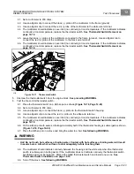
Figure 12-17
Thermostat Switch
5.
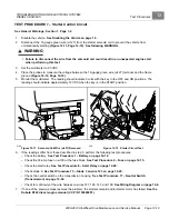
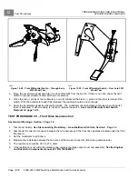
Unscrew the thermostat switch from the engine block.
See preceding WARNING.
6.
Test the fan control thermostat switch.
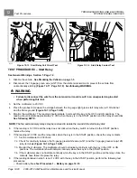
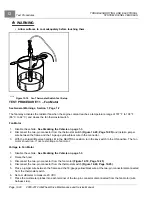
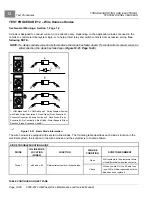
6.1. Place the thermostat switch in a kitchen pot as shown
.
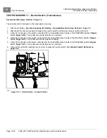
6.2. Set a multimeter to 200 ohms.
6.3. Use an alligator clip to connect the black (–) probe to the thermostat switch housing.
6.4. Use an alligator clip to connect the red (+) probe to the white wire terminal.
6.5. The multimeter should indicate an over limit (no continuity) at room temperature. If the multimeter indicates
continuity at room temperature, replace the thermostat switch.
See Thermostat Switch Removal on
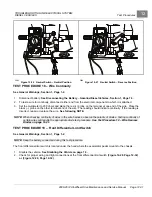
6.6. Fill the kitchen pot with water so that approximately half of the thermostat housing is submerged as shown
.
6.7. Place the kitchen pot on a stove and bring the water to a boil.
See following WARNING.
WARNING
• Hot! Do not touch hot surfaces or boiling water. Contact with hot surfaces or boiling water will result
in severe burns. Allow hot surfaces to cool adequately before touching them.
6.8. The multimeter should indicate continuity between the housing and the white wire when the thermostat
switch is submerged in boiling water. If the multimeter does not indicate continuity, the thermostat switch
has failed and must be replaced. Discard the failed thermostat switch and install a new one.
Thermostat Switch Installation on page 14-19.
6.9. Turn off the stove.
See following WARNING.
2008-2012 All-Wheel Drive Maintenance and Service Manual
Page 12-23
Summary of Contents for Carryall 295 SE
Page 2: ......
Page 20: ......
Page 28: ......
Page 58: ......
Page 66: ......
Page 100: ......
Page 122: ......
Page 150: ......
Page 157: ......
Page 190: ......
Page 197: ......
Page 236: ......
Page 284: ......
Page 386: ......
Page 394: ......
Page 442: ......
Page 452: ......
Page 454: ......
Page 455: ......
Page 456: ......

