TROUBLESHOOTING AND ELECTRICAL SYSTEM:
DIESEL VEHICLES
Test Procedures
12
2092
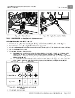
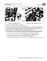
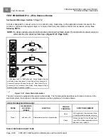
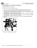
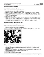
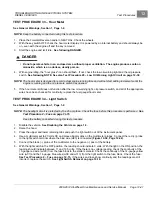
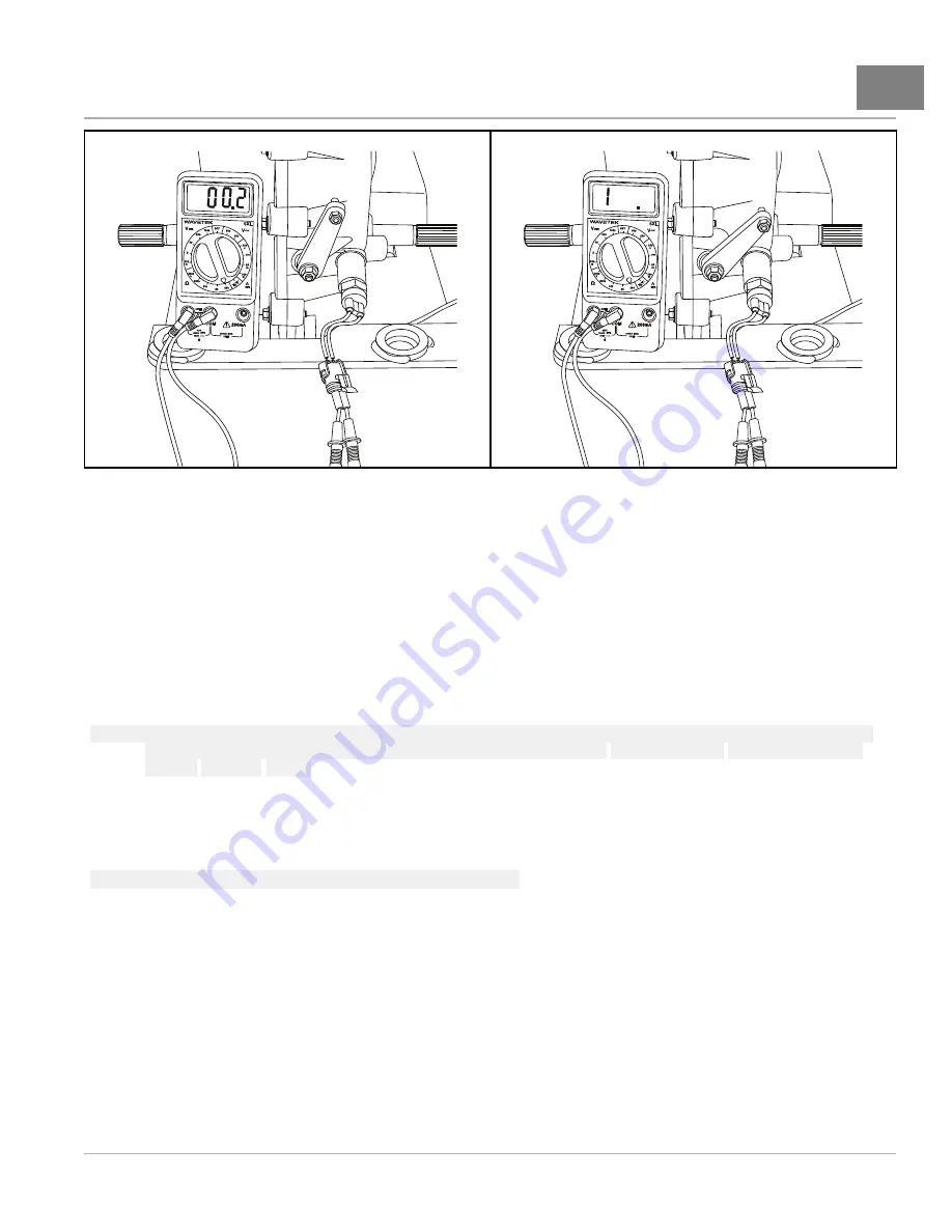
Figure 12-26
Neutral Switch – Neutral Position
2094
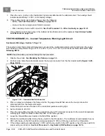
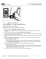
Figure 12-27
Neutral Switch – Reverse Position
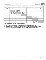
TEST PROCEDURE 18 – Wire Continuity
See General Warnings, Section 1, Page 1-2.
1.
Disconnect battery.
See Disconnecting the Battery – Gasoline/Diesel Vehicles, Section 1, Page 1-3.
2.
To test a wire for continuity, disconnect either end from the electrical component to which it is attached.
3.
Set the multimeter to 200 ohms and place the red (+) probe on the terminal at one end of the wire. Place the
black (–) probe on the other terminal end of the wire. The reading should indicate continuity. If the reading is
incorrect, repair or replace the wire.
See following NOTE.
NOTE:
When checking continuity of wires in the wire harness, observe the polarity of diodes. Testing continuity of
certain wires will require the appropriate diode test procedure.
See Test Procedure 12 – Wire Harness
TEST PROCEDURE 19 – Front Differential Limit Switch
See General Warnings, Section 1, Page 1-2.
NOTE:
Keep the battery connected during this test procedure.
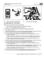
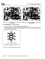
The front differential limit switch is located under the hood where the accelerator pedal mounts to the chassis.
1.
Disable the vehicle.
See Disabling the Vehicle on page 1-3.
2.
Check for proper wiring and tight connections at the front differential limit switch
2008-2012 All-Wheel Drive Maintenance and Service Manual
Page 12-31
Summary of Contents for Carryall 295 SE
Page 2: ......
Page 20: ......
Page 28: ......
Page 58: ......
Page 66: ......
Page 100: ......
Page 122: ......
Page 150: ......
Page 157: ......
Page 190: ......
Page 197: ......
Page 236: ......
Page 284: ......
Page 386: ......
Page 394: ......
Page 442: ......
Page 452: ......
Page 454: ......
Page 455: ......
Page 456: ......

