12
Test Procedures
TROUBLESHOOTING AND ELECTRICAL
SYSTEM: DIESEL VEHICLES
2093
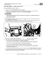
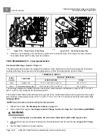
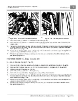
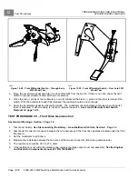
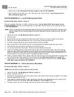
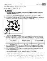
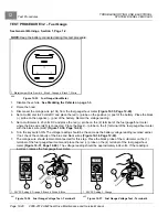
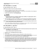
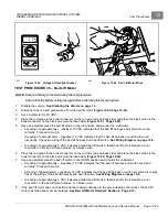
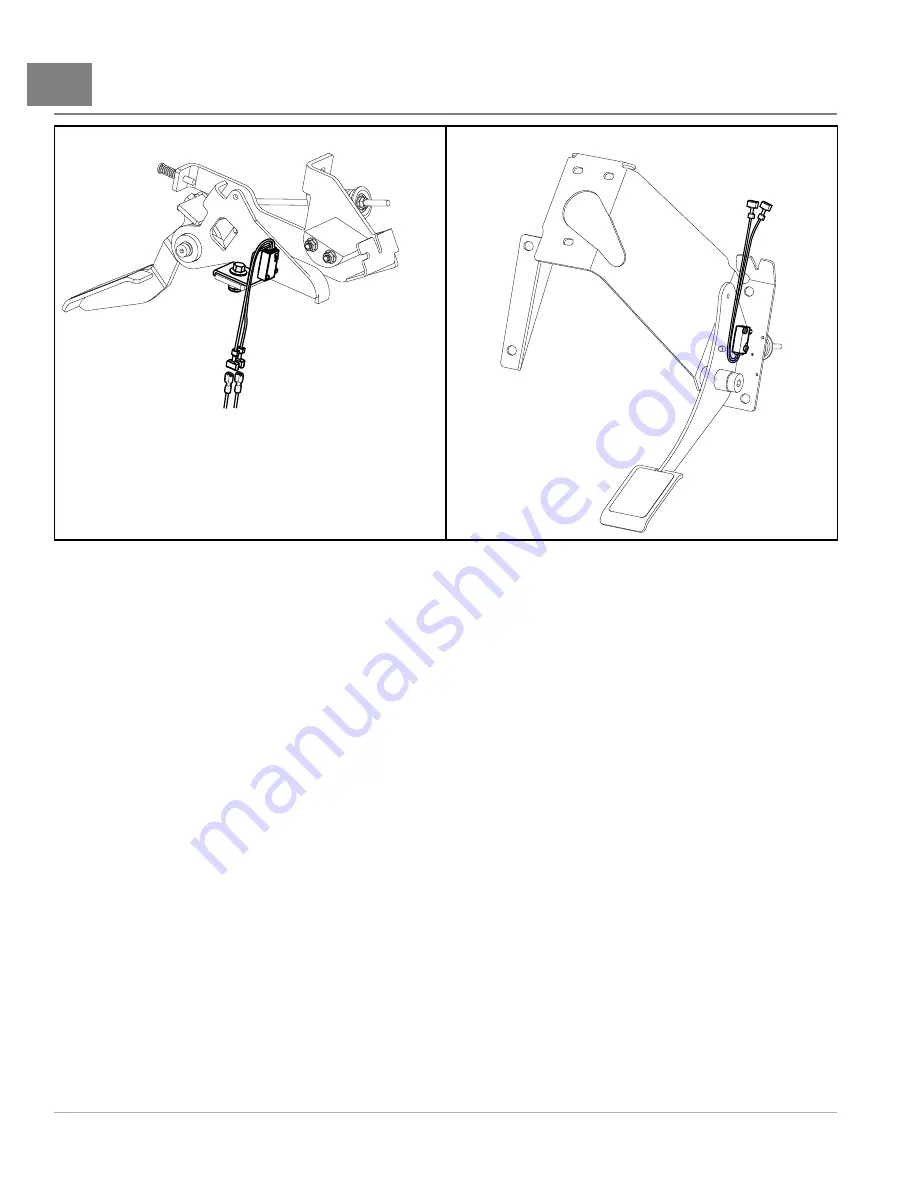
Figure 12-28
Front Differential Switch – Through Early
2010 Model Year
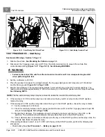
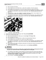
2363
Figure 12-29
Front Differential Switch – From Late 2010
Model Year
3.
Move the accelerator pedal and listen for an audible click from the switch. If there is no click, check the limit
switch for proper alignment and switch arm movement.
4.
Place the red (+) probe of the multimeter on one terminal and the black (–) probe on the other terminal of the
switch. With the accelerator pedal fully released, the reading should be no continuity.
5.
Apply the accelerator pedal to activate the switch. The multimeter should indicate continuity when the switch
lever is activated. If either reading is incorrect, replace the switch.
See Front Differential Limit Switch
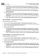
TEST PROCEDURE 20 – Front Drive Gearcase Coil
See General Warnings, Section 1, Page 1-2.
1.
Disconnect battery.
See Disconnecting the Battery – Gasoline/Diesel Vehicles, Section 1, Page 1-3.
2.
Disconnect the two-pin connector between the wire harness and the front drive gearcase located under the front
floorboard.
3.
Set the multimeter to 200 ohms.
4.
Measure the resistance between the two wires at the two-pin connector (front drive gearcase side).
5.
The resistance should be 24.7 to 27.3 ohms.
6.
If the resistance is not within the stated range, replace the large output cover sub-assembly.
See the Engines
and Drivetrain Components manual (CC P/N 102396501).
Page 12-32
2008-2012 All-Wheel Drive Maintenance and Service Manual
Summary of Contents for Carryall 295 SE
Page 2: ......
Page 20: ......
Page 28: ......
Page 58: ......
Page 66: ......
Page 100: ......
Page 122: ......
Page 150: ......
Page 157: ......
Page 190: ......
Page 197: ......
Page 236: ......
Page 284: ......
Page 386: ......
Page 394: ......
Page 442: ......
Page 452: ......
Page 454: ......
Page 455: ......
Page 456: ......

