15
Fuel System
GASOLINE ENGINE, MUFFLER, FUEL
SYSTEM, AND CLUTCHES
1
2
3
5
4
4
11
2154
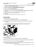
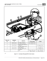
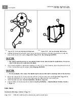
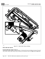
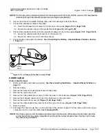
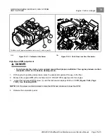
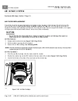
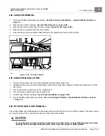
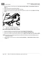
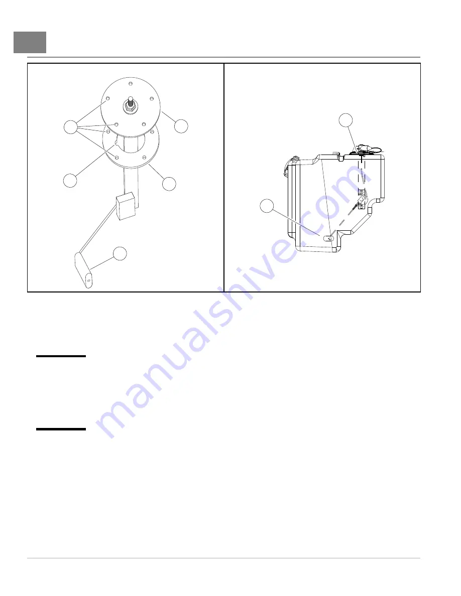
Figure 15-9
Fuel Level Sending Unit Alignment
2156
Figure 15-10
Fuel Level Sending Unit Position
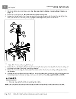
4.
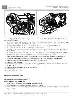
Carefully thread each hex-head screw by hand, with the ring terminal on the black ground wire (6) under the
screw head closest to the engine
.
See following CAUTION.
CAUTION
• Use only the existing screws or new plastic-thread screws made for plastics applications. Do not use
sheet metal screws as replacement hardware.
5.
Use a crisscross pattern to tighten the hardware to 9 in-lb (1 N·m). If the hardware cannot be tightened to 9 in-lb
(1 N·m), the fuel tank must be replaced.
See following CAUTION.
CAUTION
• Do not overtighten the screws. Overtightening the screws will strip the mounting holes in the fuel tank.
6.
Secure the orange wire (7) to the center post with the nut (9) previously removed
.
Tighten the hardware to 17 in-lb (1.9 N·m) and secure the rubber boot (8) to the center post.
7.
Install the passenger seat.
See Seat Installation, Section 4, Page 4-9.
8.
Connect battery and spark plug wire(s).
See Connecting the Battery – Gasoline/Diesel Vehicles, Section
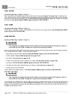
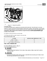
FUEL TANK
See General Warnings, Section 1, Page 1-2.
Page 15-14
2008-2012 All-Wheel Drive Maintenance and Service Manual
Summary of Contents for Carryall 295 SE
Page 2: ......
Page 20: ......
Page 28: ......
Page 58: ......
Page 66: ......
Page 100: ......
Page 122: ......
Page 150: ......
Page 157: ......
Page 190: ......
Page 197: ......
Page 236: ......
Page 284: ......
Page 386: ......
Page 394: ......
Page 442: ......
Page 452: ......
Page 454: ......
Page 455: ......
Page 456: ......


