GASOLINE ENGINE, MUFFLER, FUEL SYSTEM,
AND CLUTCHES
Clutches
15
Drive Clutch Component Inspection – Two-Weight Design
1.
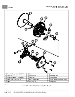
Use a feeler gauge to inspect the torque rollers (7) and replace the rollers if necessary
1.1. Use a pin driver to drive out the pin (8), which will release a pin (9) and allow the rollers (7) to slide out
of the spider (6).
1.2. Install new rollers and secure the rollers with pins.
2.
Inspect the rollers (10) and weights (11). There should be no noticeable wear. If the rollers or weights are
worn, scratched, or damaged, replace them.
2.1. Remove the bolts (12) and flex locknuts (13) that secure the rollers (10) to the spider (6) and the weights
(11) to the moveable sheave (14).
2.2. Install new rollers and weights with bolts and flex locknuts.
Drive Clutch Component Inspection – Three-Weight Design
1.
Inspect the rollers (6) and pins (7)
. Ensure they rotate freely without roughness or
loose play. If they do not, the entire drive clutch must be replaced. The rollers and pins can not be replaced.
2.
Inspect the weights (11). There should be no noticeable wear. If the weights are worn, scratched, or damaged,
replace them.
2.1. Remove the bolts (14) and flex locknuts (13) that secure the weights (11) to the moveable sheave (12).
2.2. Install new weights with bolts and flex locknuts. Tighten the locknuts to 45 in-lb (5 N·m).
Drive Clutch Assembly – Two-Weight Design
NOTE:
The drive clutch components are marked with an X to assist in correct reassembly. It is important to note the
location of the X on the components and be sure to align the X’s when assembling the drive clutch.
1.
Place the moveable sheave (14) and spider (6) onto the fixed sheave (15). Note the location of the X so the
remaining components with an X can be aligned
.
2.
Use a spider removal tool (CC P/N 102607501) to tighten the moveable sheave and spider to 225 ft-lb (305 N·m).
3.
Install the spring (5) onto the shaft.
4.
Install the cover (4) onto the shaft.
5.
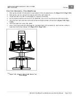
Align the plate that has holes in the cover with arrows on the same side. Pull the moveable sheave upward and
start threading the bolts with washers into holes.
See following NOTE.
NOTE:
Keep the cover as square to the post as possible to minimize wear between the post and cover.
6.
Use a crisscross pattern to continue tightening the hardware.
7.
Tighten the bolts to 120 in-lb (14 N·m).
Drive Clutch Assembly – Three-Weight Design
NOTE:
The drive clutch components are marked with an X to assist in correct reassembly. It is important to note the
location of the X on the components and be sure to align the X’s when assembling the drive clutch.
1.
Place the moveable sheave (12), shim (10) and spider (5) onto the fixed sheave (15). Note the location of the X
so the remaining components with an X can be aligned
.
2.
Use a spider removal tool (P/N 103865301) to tighten the moveable sheave and spider to 265 ft-lb (359 N·m).
3.
Install the spacer (4) and spring (5) onto the shaft.
4.
Place the cover plate (2) onto the shaft.
2008-2012 All-Wheel Drive Maintenance and Service Manual
Page 15-37
Summary of Contents for Carryall 295 SE
Page 2: ......
Page 20: ......
Page 28: ......
Page 58: ......
Page 66: ......
Page 100: ......
Page 122: ......
Page 150: ......
Page 157: ......
Page 190: ......
Page 197: ......
Page 236: ......
Page 284: ......
Page 386: ......
Page 394: ......
Page 442: ......
Page 452: ......
Page 454: ......
Page 455: ......
Page 456: ......

