17
Rear Axle – 2008-2011 Models
DRIVETRAIN COMPONENTS
6.
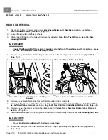
Secure the rear receiver hitch to the inside of the swing arms and axle at four locations with new bolts and
washers. If new bolts are not available, clean existing bolts and add Loctite 2760 per instructions. Finger-tighten
the hardware.
7.
Tighten all eight axle mounting bolts to 95 ft-lb (129 N·m).
8.
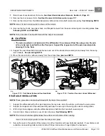
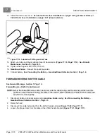
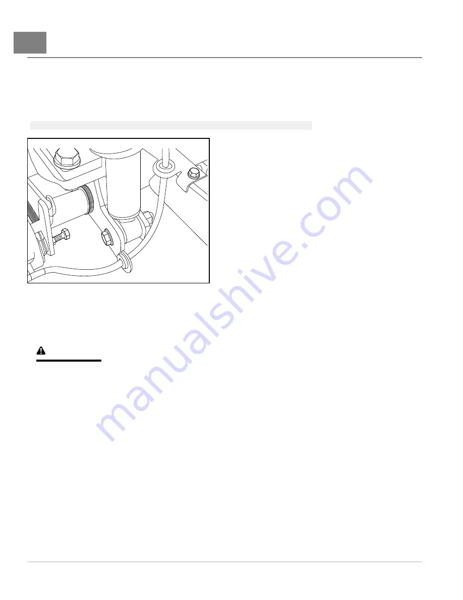
Secure shock absorbers to axle
.
See following NOTE.
NOTE:
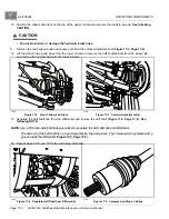
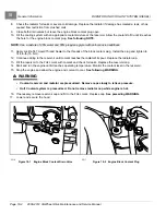
Hydraulic brake line brackets fit to the right side of both lower shock mounts.
2206
Figure 17-15
Lower Driver Side Shock Mount
9.
Install both rear brake calipers to axle.
See Rear Brake Caliper Installation, Section 6, Page 6-9.
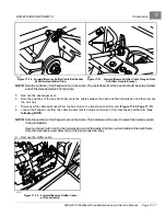
10. Secure the hydraulic brake lines to the rubber grommets at all frame locations.
See following CAUTION.
CAUTION
• Do not kink, twist, or damage the hydraulic brake lines.
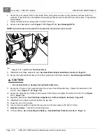
11. Secure the P-clamp to the hydraulic brake line on top of the differential body. Tighten the hardware to 132
in-lb (15 N·m)
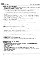
12. Secure the hydraulic line T-fitting to the receiver hitch frame and tighten the bolt to 48 in-lb (7 N·m)
13. Adjust the park brake.
See Park Brake Adjustment – At Rear Calipers, Section 6, Page 6-27.
14. Install both rear wheels and finger-tighten the lug nuts.
15. Lower the rear of the vehicle.
16. Use a crisscross pattern to tighten the lug nuts on both rear wheels to 85 ft-lb (115 N·m).
17.
Gasoline vehicles:
Connect the spark plug wires.
18. Connect battery.
See Connecting the Battery – Gasoline/Diesel Vehicles, Section 1, Page 1-4.
Page 17-10
2008-2012 All-Wheel Drive Maintenance and Service Manual
Summary of Contents for Carryall 295 SE
Page 2: ......
Page 20: ......
Page 28: ......
Page 58: ......
Page 66: ......
Page 100: ......
Page 122: ......
Page 150: ......
Page 157: ......
Page 190: ......
Page 197: ......
Page 236: ......
Page 284: ......
Page 386: ......
Page 394: ......
Page 442: ......
Page 452: ......
Page 454: ......
Page 455: ......
Page 456: ......

