17
Rear Axle – Starting 2012 Model Year
DRIVETRAIN COMPONENTS
NOTE:
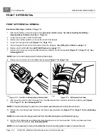
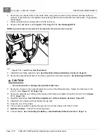
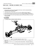
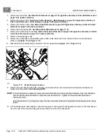
Use a 1/4-inch roll pin punch to drive out the roll pin.
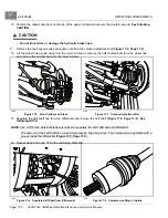
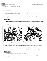
10. Remove the four bolts, washers, and flanged locknuts securing axle to trailing arms and lateral links.
Trailing Arms and Lateral Links – Starting 2012 Model Year on page 9-6.
Discard locknuts.
See following
NOTE and CAUTION.
NOTE:
This procedure is best performed with the help of an assistant.
CAUTION
• The axle assembly is not balanced at the differential. Once released from the suspension, the axle
is free to tip and could fall from the floor jack. Support the longest end of the axle assembly while
lowering it to the floor.
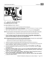
11. Support the rear driveshaft and slide the rear axle out of the driveshaft universal joint and out the rear of the
vehicle.
See preceding NOTE.
REAR AXLE INSTALLATION
NOTE:
These procedures are best performed with the help of an assistant.
1.
Place rear axle on floor jack, with differential resting on jack pad, and roll axle under rear suspension.
2.
Support the long axle tube and raise axle up to trailing arms and lateral links.
3.
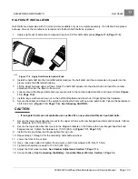
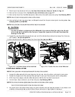
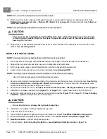
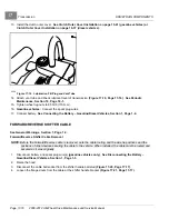
With roll pin holes aligned, slide differential pinion shaft into driveshaft universal joint.
4.
Center roll pin holes and drive a new roll pin into place.
See following NOTE.
NOTE:
The roll pin should be slightly below the surface on both sides of the coupling.
Use a 1/4-inch roll pin punch to drive the roll pin into place.
5.
Secure axle to trailing arms and lateral links at four locations with bolts, washers and new locknuts.
Arms and Lateral Links – Starting 2012 Model Year on page 9-6.
If new locknuts are not available, clean
existing bolts and add Loctite 2760 per instructions.
6.
Secure shock absorbers to axle.
See Rear Coil-Over Shock Absorber – Starting 2012 Model Year on page 9-4.
7.
Install both rear brake calipers to axle
. Tighten new bolts to 36 ft-lb (49 N·m).
8.
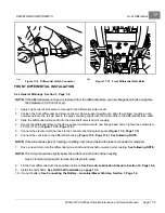
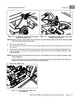
Anchor the hydraulic brake hose to rear axle at all original locations
See following
CAUTION.
Tighten P-clamp bolt to 84 in-lb (9.5 N·m).
CAUTION
• Do not kink, twist, or damage the hydraulic brake lines.
9.
Install both rear wheels and finger-tighten the lug nuts.
10. Lower the rear of the vehicle.
11. Use a crisscross pattern to tighten the lug nuts on both rear wheels.
See Wheel Installation on page 8-2.
12. Ensure differential has appropriate type and volume of oil.
See Gearcase Lubrication on page 10-13.
13.
Gasoline vehicles:
Connect the spark plug wires.
14. Connect battery.
See Connecting the Battery – Gasoline/Diesel Vehicles, Section 1, Page 1-4.
Page 17-12
2008-2012 All-Wheel Drive Maintenance and Service Manual
Summary of Contents for Carryall 295 SE
Page 2: ......
Page 20: ......
Page 28: ......
Page 58: ......
Page 66: ......
Page 100: ......
Page 122: ......
Page 150: ......
Page 157: ......
Page 190: ......
Page 197: ......
Page 236: ......
Page 284: ......
Page 386: ......
Page 394: ......
Page 442: ......
Page 452: ......
Page 454: ......
Page 455: ......
Page 456: ......

