19
Attachment Interface
HYDRAULIC ATTACHMENT SYSTEM
1.
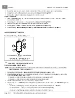
Lower the attachment arm to the ground and tilt the attachment interface forward
2.
Stop the engine, put the Forward/Reverse Handle in NEUTRAL, engage the park brake, unfasten your seat
belt, and exit the vehicle.
3.
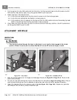
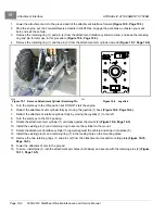
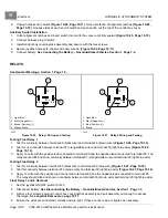
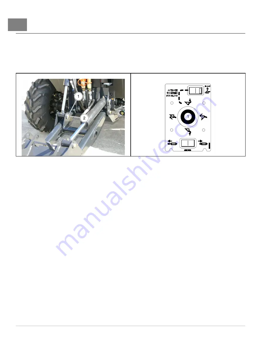
Remove the retaining ring (1) and pin (2) from the attachment interface cylinder rod end, and keep the retaining
ring and pin for later use in this procedure
4.
Remove the retaining ring (1) and the pin (2) from the attachment arm cylinder rod end
2226
Figure 19-7
Remove Attachment Cylinder Retaining Pin
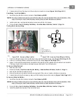
256
Figure 19-8
Joystick
5.
Turn the start key to the ON position but DO NOT start the engine.
6.
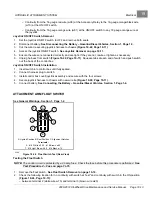
Retract the attachment arm cylinder fully by moving the joystick (1) back
.
7.
Retract the attachment interface cylinder fully by moving the joystick (1) to the left.
8.
Turn the start key to the OFF position.
9.
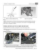
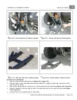
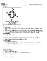
Rotate the attachment arm cylinder (1) vertically against the mount (2)
10. Install the existing pin (3) and retaining ring to secure the cylinder to the mount.
11. Rotate the attachment interface cylinder (5) upward against the vehicle and snap it into place (8).
12. Install the existing pin (6) and retaining ring (7) in the locking hole on the mounting plate.
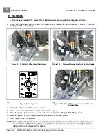
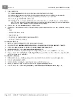
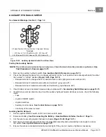
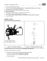
13. Remove the two retaining rings (1) and pins (2) from the attachment arms and mounting plate
.
14. Lower the attachment arm to the ground.
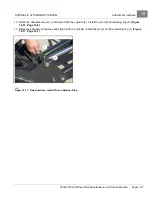
15. To store, install pins (1) into the attachment arm holes (both sides) and secure with the retaining pins (2)
Page 19-4
2008-2012 All-Wheel Drive Maintenance and Service Manual
Summary of Contents for Carryall 295 SE
Page 2: ......
Page 20: ......
Page 28: ......
Page 58: ......
Page 66: ......
Page 100: ......
Page 122: ......
Page 150: ......
Page 157: ......
Page 190: ......
Page 197: ......
Page 236: ......
Page 284: ......
Page 386: ......
Page 394: ......
Page 442: ......
Page 452: ......
Page 454: ......
Page 455: ......
Page 456: ......

