19
Attachment Interface
HYDRAULIC ATTACHMENT SYSTEM
WARNING
• Do not have hands in the area of the cylinders when extending or retracting the cylinders.
6.
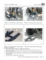
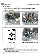
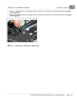
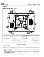
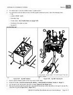
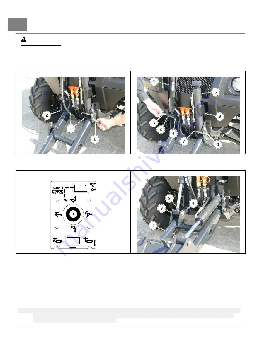
Remove the two retaining rings (4 and 7) and pins (3 and 6) that secure the two cylinders (1 and 5) to the mount
(2)
2228
Figure 19-13
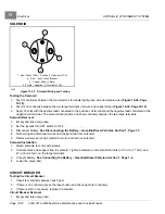
Align the Attachment Arm Holes
2232
Figure 19-14
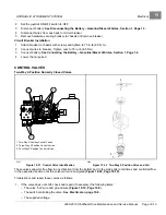
Remove Retainer Pins from Both Cylinders
256
Figure 19-15
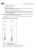
Joystick
2234
Figure 19-16
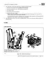
Raise Attachment Arm, Install Pin, and
Retainer Ring
7.
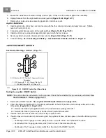
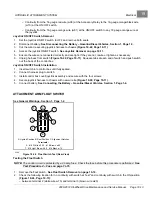
Swing the attachment interface cylinder down.
8.
Turn the key to the ON position but DO NOT start the engine.
9.
Move the joystick (1) forward to extend the attachment arm cylinder
10. Move the joystick (1) to the right to extend the attachment interface cylinder.
11. Turn the key to the OFF position.
NOTE:
When aligning the cylinders to the attachment arm and interface during installation, the cylinders may need
to be retracted slightly to relieve the hydraulic pressure. Do not have hands in the area of the cylinders
when extending or retracting the cylinders.
Page 19-6
2008-2012 All-Wheel Drive Maintenance and Service Manual
Summary of Contents for Carryall 295 SE
Page 2: ......
Page 20: ......
Page 28: ......
Page 58: ......
Page 66: ......
Page 100: ......
Page 122: ......
Page 150: ......
Page 157: ......
Page 190: ......
Page 197: ......
Page 236: ......
Page 284: ......
Page 386: ......
Page 394: ......
Page 442: ......
Page 452: ......
Page 454: ......
Page 455: ......
Page 456: ......


