19
Electrical
HYDRAULIC ATTACHMENT SYSTEM
JOYSTICK
See General Warnings, Section 1, Page 1-2.
2
1
4
3
6
8
14
16
9
11
A
B
C
D
F
E
13
12
10
15
5
7
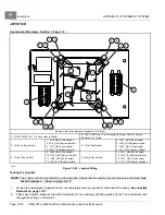
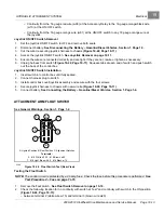
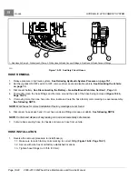
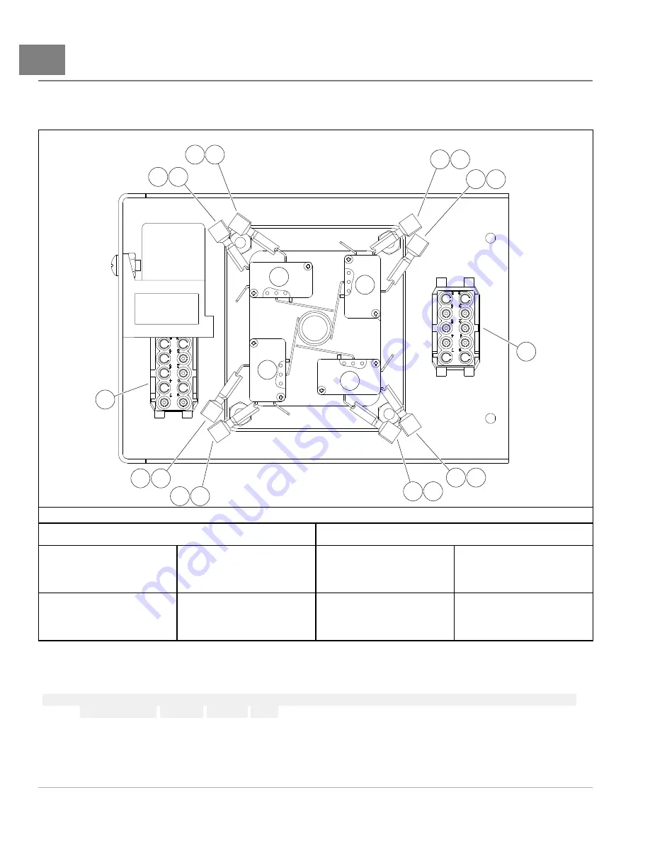
Bottom View (Wire Harness Removed For Clarity)
A. FLOAT SWITCH: 8 - Pin Connector (4 Wires)
B. AUX SWITCH: 8 - Pin Connector (6 Wires) ON-OFF Switch
Removed For Clarity
C. Lift Down (Top Switch)
1. W18_ORG (Top Switch)
2. W14_ORG (Bottom Switch)
3. W17_GRN (Top Switch)
4. W38_YEL (Bottom Switch)
D. Tilt In (Top Switch)
5. W21_GRN (Top Switch)
6. W53_PUR (Bottom Switch)
7. W02_ORG (Top Switch)
8. W11_ORG (Bottom Switch)
E. Tilt Out (Top Switch)
9. W80_ORG (Top Switch)
10. W78_ORG (Bottom Switch)
11. W19_GRN (Top Switch)
12. W39_BLU (Bottom Switch)
F. Lift Up (Top Switch)
13. W13_GRN (Top Switch)
14. W37_YEL (Bottom Switch)
15. W79_ORG (Top Switch)
16. W77_ORG (Bottom Switch)
2236
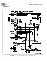
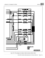
Figure 19-20
Joystick Wiring
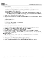
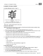
Testing the Joystick
NOTE:
The control circuit is protected by a 20-amp fuse. Check the fuse before this procedure is performed.
See
Test Procedure 2 – Fuse on page 12-15
1.
Access the underside of joystick but do not completely remove joystick or disconnect the wiring.
2.
Check each switch, between the wired terminals, for no continuity with the joystick at “rest” and continuity with
the joystick acting on the switch.
Page 19-10
2008-2012 All-Wheel Drive Maintenance and Service Manual
Summary of Contents for Carryall 295 SE
Page 2: ......
Page 20: ......
Page 28: ......
Page 58: ......
Page 66: ......
Page 100: ......
Page 122: ......
Page 150: ......
Page 157: ......
Page 190: ......
Page 197: ......
Page 236: ......
Page 284: ......
Page 386: ......
Page 394: ......
Page 442: ......
Page 452: ......
Page 454: ......
Page 455: ......
Page 456: ......

