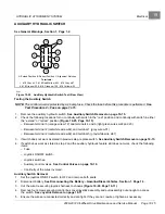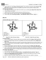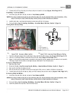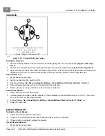
HYDRAULIC ATTACHMENT SYSTEM
Electrical
19
5.
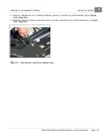
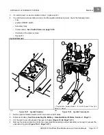
Locate and pull or pry the relay out of the multi-pin connector to remove
Float Relay 1 and 2 Installation
1.
Insert the relay into the multi-pin connector.
See following NOTE.
NOTE:
The relay contacts are keyed to ensure that the relay can only be installed in the correct orientation. If the
relay is not easy to insert, rotate the relay until the correct contact orientation is obtained.
2.
Install control box cover/joystick assembly and secure with the four screws.
3.
Connect battery.
See Connecting the Battery – Gasoline/Diesel Vehicles, Section 1, Page 1-4.
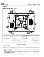
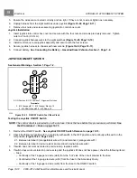
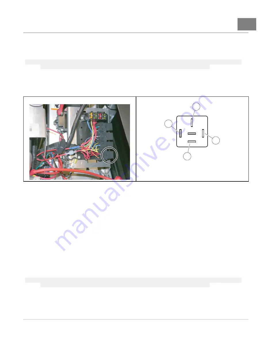
Testing the Accessory Relay
30
85
86
87a
87
1
2
4
3
1. Red
2. Black (Negative [–)
3. Orange (Positive [+])
4. Red
2244
Figure 19-28
Accessory Relay Location
2245
Figure 19-29
Accessory Relay Wiring and Testing
1.
Test for continuity between terminal 85 (black wire) and terminal 86 (orange wire)
.
2.
Test for no continuity between terminals 87 and 30 (red wires)
.
3.
Apply 12 volts with the positive lead connected to terminal 86 and the negative lead connected to terminal 85.
The relay should click and show continuity between terminals 87 and 30 (red wires).
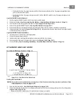
Accessory Relay Removal
1.
Remove driver seat.
2.
Disconnect battery.
See Disconnecting the Battery – Gasoline/Diesel Vehicles, Section 1, Page 1-3.
3.
Remove the electrical component cover.
4.
Ensure the wires are connected correctly and are tight. If they are not, rewire or tighten as necessary.
5.
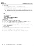
Locate and pull or pry the accessory relay out of the multi-pin connector to remove
.
Accessory Relay Installation
1.
Insert the relay into the multi-pin connector.
See following NOTE.
NOTE:
The relay contacts are keyed to ensure that the relay can only be installed in the correct orientation. If the
relay is not easy to insert, rotate the relay until the correct contact orientation is obtained.
2.
Connect battery.
See Connecting the Battery – Gasoline/Diesel Vehicles, Section 1, Page 1-4.
3.
Install the electrical component cover and driver seat.
2008-2012 All-Wheel Drive Maintenance and Service Manual
Page 19-17
Summary of Contents for Carryall 295 SE
Page 2: ......
Page 20: ......
Page 28: ......
Page 58: ......
Page 66: ......
Page 100: ......
Page 122: ......
Page 150: ......
Page 157: ......
Page 190: ......
Page 197: ......
Page 236: ......
Page 284: ......
Page 386: ......
Page 394: ......
Page 442: ......
Page 452: ......
Page 454: ......
Page 455: ......
Page 456: ......

