U.S.A.:
MONARCH HYDRAULICS, INC.
P.O. Box 1764, Grand Rapids, Michigan 49501-1764, U.S.A.
Telephone: (616) 458-1306
Telefax: (616) 458-1616
http://www.monarchhyd.com
Form No. 2384-01
CANADA:
FLUID-PACK INTERNATIONAL LIMITED
A Part of the Monarch Hydraulics Group
460 Newbold St., London, Ontario, Canada N6E 1K3
Telephone: (519) 686-5900
Telefax: (519) 686-8976
Litho in U.S.A.
Monarch Hydraulics, Inc.
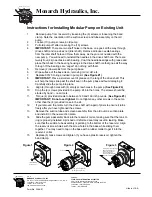
Instructions for Installing Modular Pump on Existing Unit
1.
Remove pump from reservoir by loosening the (6) screws or loosening the band
clamp. Note the orientation of the suction screen and tube assembly on the old
pump.
2.
Loosen (10) pump screws in old pump.
3.
Pull old pump off after loosening the (10) screws.
4.
IMPORTANT:
There are two shaft holes in the base, one goes all the way through
(drive shaft) and one does not (idler shaft). Remove all loose needle bearings
from the idler shaft hole and throw them away, as they are not needed with the
new pump. You will need to reinstall the needles in the drive shaft hole. There are
twenty-four (24) needles in each bearing. Coat the needle bearings with grease and
place them back in the bearing housings in the drive shaft hole that goes all the way
through. If the bearings are caged do nothing with them.
5.
Remove (2) dowel pins from the pump base.
6.
Wipe surface of the base clean, removing old oil, dirt, etc.
7.
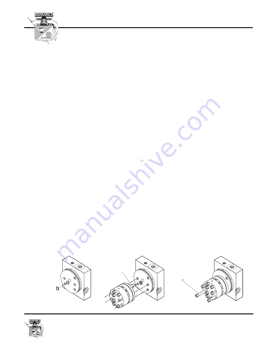
Replace 00120 O-ring provided in pump kit.
(See Figure #1)
8.
IMPORTANT:
Place a small amount of grease on the tang of the drive shaft. This
will help the tang slide past the shaft seal in the pump base without damaging it.
Carefully slide the pump into place.
9.
Align (4) through holes with (4) empty screw holes in the pump.
(See Figure #2)
10.
Drop the (4) screws provided in the pump kit into the holes. The screws should be
started by hand -- no air tools.
11.
Torque (4) provided screws to between
140
and
160
inch pounds. (
See Figure #3)
IMPORTANT: Do not over tighten!
Do not tighten any other screws in the pump
other than the (4) provided loose in the kit.
12.
If you removed the motor, turn the drive shaft with a pair of pliers to ensure it turns
freely after you have tightened the screws.
13.
Remove the suction tube and screen assembly from the old pumps suction plate
and install it in the new suction plate.
14.
Slide the pump assembly back into the reservoir collar, making sure that the tank O-
ring is properly installed. A pinched or deformed seal may result in leaking. Make
sure that the suction tube assembly is pointing to the bottom of the reservoir. Align
the reservoir screw holes with the screw holes in the base while sliding them
together. You may need to tap on the base with a rubber mallet to get it into the
reservoir collar.
15.
Replace (6) tank screws and tighten. If you have a plastic reservoir, tighten the
band clamp.
Align (4) Through Holes
With (4) Screw Holes
Drive Shaft
Install (4) Screws Through
Pump And Into Base.
Torque (4) Screws To
140-160 Inch Lbs.
Folllowing The Number
Sequence Shown.
7
9
8
10
Install O-Ring
#00120 Here
Figure 1
Figure 2
Figure 3
Summary of Contents for Carryall 295 SE
Page 2: ......
Page 20: ......
Page 28: ......
Page 58: ......
Page 66: ......
Page 100: ......
Page 122: ......
Page 150: ......
Page 157: ......
Page 190: ......
Page 197: ......
Page 236: ......
Page 284: ......
Page 386: ......
Page 394: ......
Page 442: ......
Page 452: ......
Page 454: ......
Page 455: ......
Page 456: ......

