6
Brake Pads and Caliper – 2008-2011 Models
HYDRAULIC AND PARK BRAKE SYSTEMS
Front Brake Pad Installation
NOTE:
To help prevent noise, a silicone-based brake lubricant may be applied to the surfaces (on the back side of
the brake pads) that contact the caliper. A thin film may also be applied to the slide-pins. Always follow
lubricant manufacturer’s directions.
WARNING
• To reduce the possibility of diminished brake performance or failure, never use petroleum-based
lubricants on brake system components, and ensure lubricant does not contact friction surfaces of
brake pads or rotors.
1.
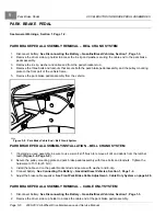
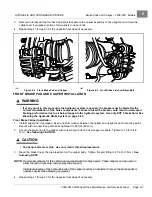
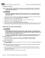
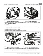
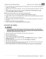
Install the brake pads and install the socket-head slide-pin bolts through top and bottom holes of pads. Tighten
the hardware to 32 ft-lb (43 N·m).
See preceding NOTE and WARNING.
2.
Install the tire and wheel. Finger-tighten the lug nuts.
3.
Lower the vehicle and use a crisscross pattern to tighten the lug nuts to 85 ft-lb (115 N·m).
4.
Repeat steps 1 through 3 for the opposite front wheel.
5.
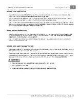
Inspect the brake system.
See Brake System Inspection on page 6-1.
6.
Burnish the new pads before initial vehicle operation. On a flat, open surface, accelerate the vehicle to moderate
speed, then apply the brakes under modest, steady pressure. Repeat this procedure for eight to twelve times.
REAR BRAKE PAD AND CALIPER REMOVAL
WARNING
• If at any point in this procedure the hydraulic system is opened, the brakes must be bled after the
correct reinstallation of the brake components. Failure to bleed the brakes could result in decreased
braking performance due to air being trapped in the hydraulic system. Use only DOT 5 brake fluid. See
Bleeding the Hydraulic Brake System on page 6-24.
• Prior to servicing hydraulic brakes, thoroughly clean the vehicle, paying particular attention to areas
immediately surrounding hydraulic connections, to prevent dirt or debris from entering system.
Rear Brake Pad Removal
1.
Lift and support the rear of vehicle and remove the wheel.
See Lifting The Vehicle on page 3-9.
2.
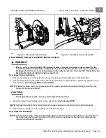
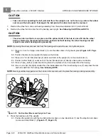
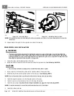
Remove the two socket-head slide-pin bolts securing the top and bottom of the two brake pads.
3.
Remove the brake pads.
Rear Brake Caliper Removal
1.
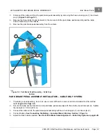
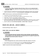
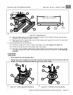
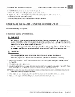
Remove the banjo bolt and copper washers that secure the brake line to the caliper body
See following NOTE.
NOTE:
Place a clean, tray-type container below the caliper and brake line assembly to catch brake fluid when the
brake line and caliper body are separated.
2.
Place a plastic bag over the hose fitting to prevent dirt and debris from entering the hydraulic brake system.
3.
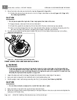
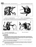
Remove and discard the two hex-head bolts that secure the caliper assembly to the axle tube and remove the
caliper
4.
Repeat steps 1 through 3 for the opposite rear wheel if necessary.
Page 6-8
2008-2012 All-Wheel Drive Maintenance and Service Manual
Summary of Contents for Carryall 295 SE
Page 2: ......
Page 20: ......
Page 28: ......
Page 58: ......
Page 66: ......
Page 100: ......
Page 122: ......
Page 150: ......
Page 157: ......
Page 190: ......
Page 197: ......
Page 236: ......
Page 284: ......
Page 386: ......
Page 394: ......
Page 442: ......
Page 452: ......
Page 454: ......
Page 455: ......
Page 456: ......

