HYDRAULIC AND PARK BRAKE SYSTEMS
Brake Disc and Hub – 2008-2011 Models
6
3
2
1
1
10
10
5
7
1/2 in.
(12 mm)
Press ram
.281 in.
(7 mm)
Radius
2.835 in. (72 cm)
2.909 in. Max. (73.9 cm Max.)
2030
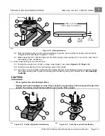
Figure 6-11
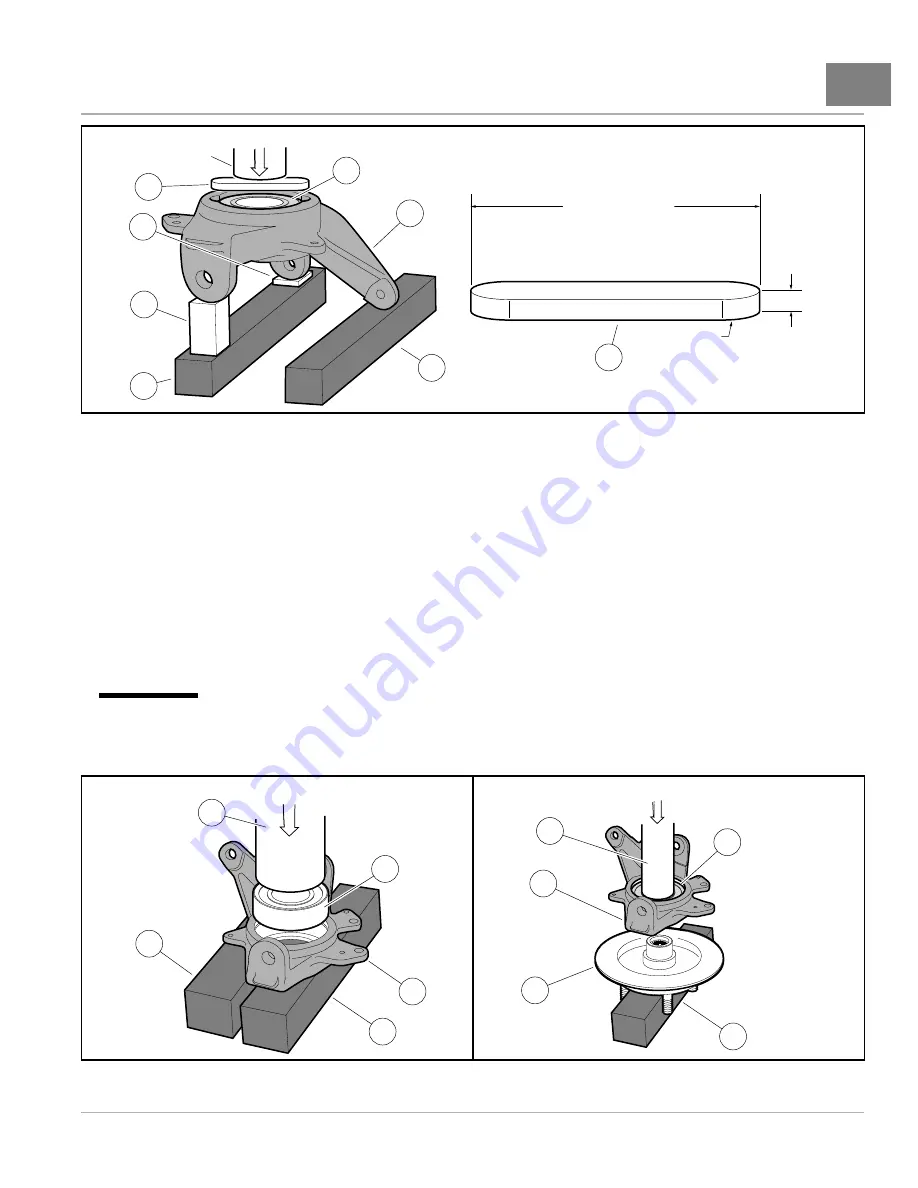
Bearing Removal
9.2. Shim the ball joint arms (2 and 3) with steel blocks to provide a level surface for bearing removal (block
2 height is 9/16" and block 3 height is 1-11/16").
9.3. Make special bar (10), that fits inside cutouts of the bearing cavity opening (7), to rest on the outer race of
the bearing. Press out bearing.
10. Install a new bearing on the disc and hub.
10.1. Position the upright on 2 x 2-inch, or larger, steel blocks (1) as shown
10.2. Position a new bearing (7) into the bearing cavity of the upright.
10.3. Use a bar or rod (8) slightly smaller than the outside diameter of the bearing, but large enough to engage
the outside bearing race, to press the bearing into the bearing cavity until it bottoms out.
See following
CAUTION.
CAUTION
• Press against the entire bearing surface.
• Bearing must seat completely in cavity. There should be no gap between the bearing and the lip of the
upright. The bearing should be flush with the non-lip side of the upright.
1
1
8
5
7
1
8
5
6
7
2031
Figure 6-12
Position Upright for New Bearing
2032
Figure 6-13
Press Disc and Hub into Bearing
2008-2012 All-Wheel Drive Maintenance and Service Manual
Page 6-13
Summary of Contents for Carryall 295 SE
Page 2: ......
Page 20: ......
Page 28: ......
Page 58: ......
Page 66: ......
Page 100: ......
Page 122: ......
Page 150: ......
Page 157: ......
Page 190: ......
Page 197: ......
Page 236: ......
Page 284: ......
Page 386: ......
Page 394: ......
Page 442: ......
Page 452: ......
Page 454: ......
Page 455: ......
Page 456: ......

