6
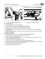
Brake Disc and Hub – 2008-2011 Models
HYDRAULIC AND PARK BRAKE SYSTEMS
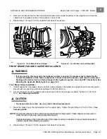
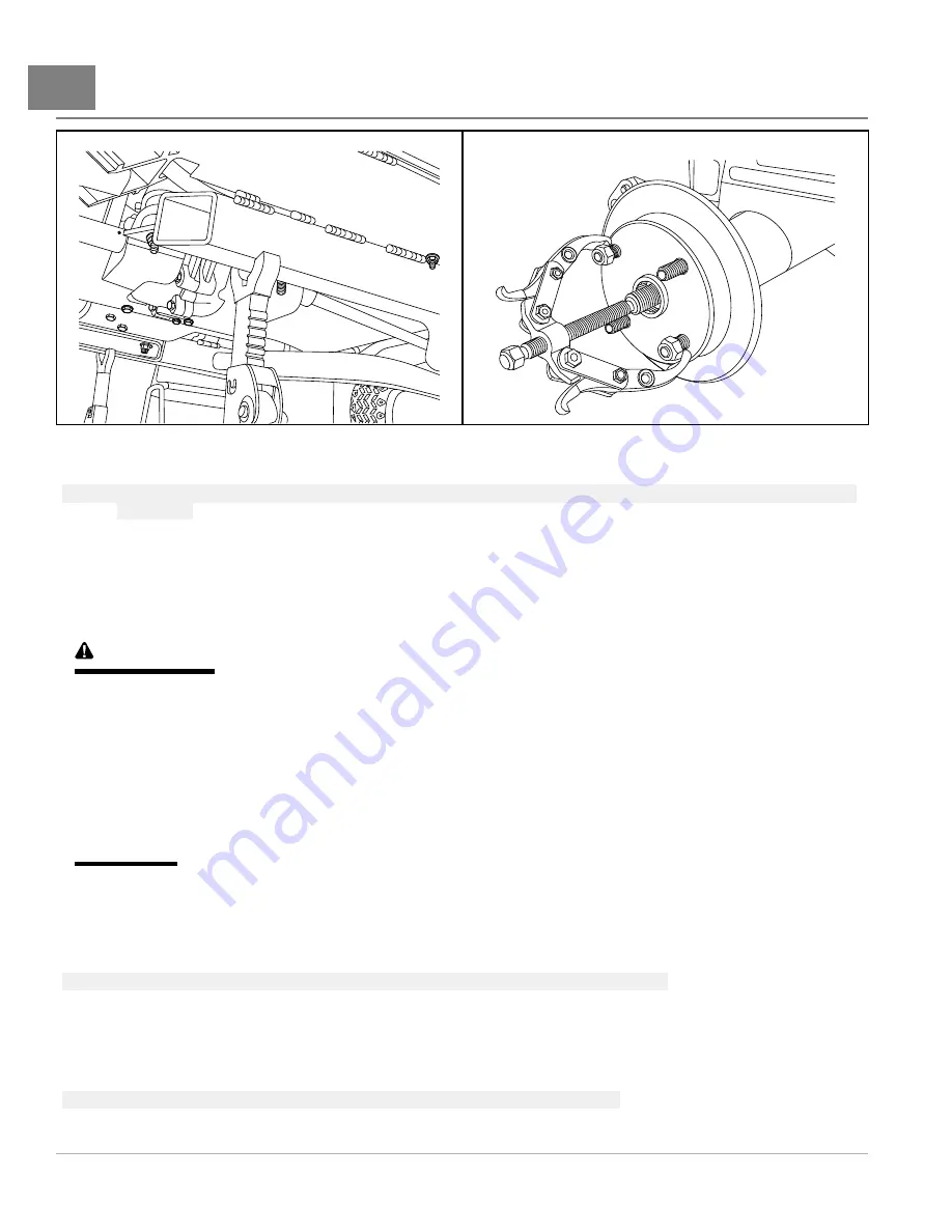
2034
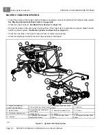
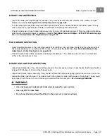
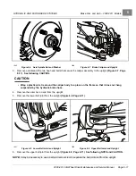
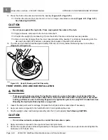
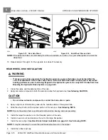
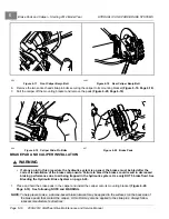
Figure 6-15
Rear Axle Stand
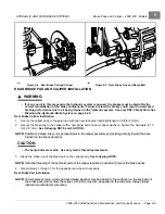
2036
Figure 6-16
Rear Wheel Disc and Hub
NOTE:
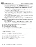
If the wheel hub does not slide easily from the axle spindle, use a two or four-jaw wheel puller to remove the
wheel hub.
10. Repeat steps 2 through 9 for the opposite rear wheel if necessary.
REAR WHEEL DISC INSTALLATION
WARNING
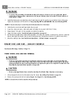
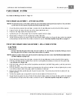
• If at any point in this procedure the hydraulic system is opened, the brakes must be bled after the
correct reinstallation of the brake components. Failure to bleed the brakes could result in decreased
braking performance due to air being trapped in the hydraulic system. Use only DOT 5 brake fluid. See
Bleeding the Hydraulic Brake System on page 6-24.
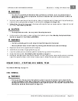
1.
Clean the spline and threaded portion of the axle.
2.
Apply anti-seize compound to both the axle and wheel hub splined area.
See following CAUTION.
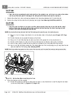
CAUTION
• Do not allow anti-seize compound to contact the brake disc or pads.
3.
Apply a light coat of lubrication grease to the outside surface of the splined hub.
4.
Slide the wheel hub onto the splined portion of the axle end.
See following NOTE.
NOTE:
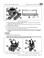
Ensure the splined hub is positioned to slide into the bearing and seal assembly.
5.
Install the large flat washer onto the threaded portion of the axle.
6.
Install a new axle nut and advance the nut to the large flat washer.
7.
Install the rear caliper.
See Rear Brake Caliper Installation on page 6-9. See following NOTE.
NOTE:
It may be necessary to loosen the park brake adjuster arm on the caliper.
8.
Install the rubber dust cap.
Page 6-16
2008-2012 All-Wheel Drive Maintenance and Service Manual
Summary of Contents for Carryall 295 SE
Page 2: ......
Page 20: ......
Page 28: ......
Page 58: ......
Page 66: ......
Page 100: ......
Page 122: ......
Page 150: ......
Page 157: ......
Page 190: ......
Page 197: ......
Page 236: ......
Page 284: ......
Page 386: ......
Page 394: ......
Page 442: ......
Page 452: ......
Page 454: ......
Page 455: ......
Page 456: ......

