17
Half Shafts
DRIVETRAIN COMPONENTS
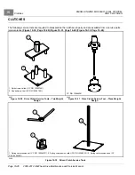
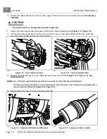
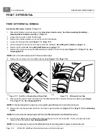
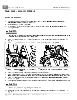
10. Position the caliper and discs on the top of the upper A-frame and secure them with a wire tie.
See following
CAUTION.
CAUTION
• Do not kink, twist, or damage the hydraulic brake lines.
11.
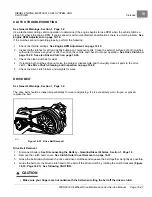
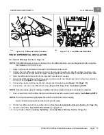
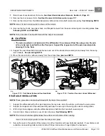
Remove the two flanged bolts and square nuts from the camber adjustment bar
.
12. Lift the wheel hub up and away from the lower A-frame to remove the half shaft spindle from the wheel hub
and remove the camber bar from the lower A-frame.
1896
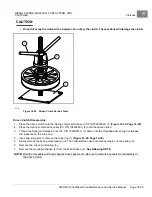
Figure 17-2
Front Caliper and Discs
2193
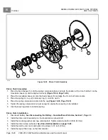
Figure 17-3
Camber Adjustment Bar
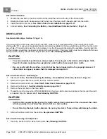
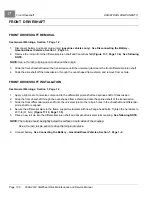
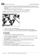
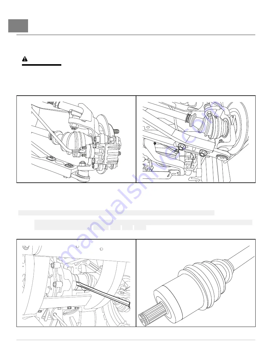
13. Separate the half shaft hub from the differential and remove the half shaft
See
following NOTE.
NOTE:
Use a 5/16-inch wide flat blade screwdriver to separate the half shaft hub and differential.
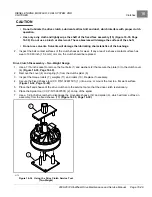
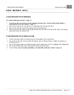
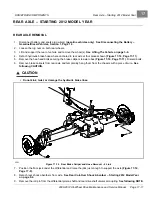
The hub end of the half shaft has a round compression ring and groove. The compression ring mates with a
groove inside the differential
14. Repeat steps 9 through 15 for the remaining half shaft.
2194
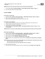
Figure 17-4
Separate Half Shaft from Differential
2195
Figure 17-5
Compression Ring on Spline
Page 17-2
2008-2012 All-Wheel Drive Maintenance and Service Manual
Summary of Contents for Carryall 295 SE
Page 2: ......
Page 20: ......
Page 28: ......
Page 58: ......
Page 66: ......
Page 100: ......
Page 122: ......
Page 150: ......
Page 157: ......
Page 190: ......
Page 197: ......
Page 236: ......
Page 284: ......
Page 386: ......
Page 394: ......
Page 442: ......
Page 452: ......
Page 454: ......
Page 455: ......
Page 456: ......

