ACCELERATOR AND BRAKE PEDAL ASSEMBLIES
Brake Pedal
5
BRAKE PEDAL
See General Warnings, Section 1, Page 1-2.
BRAKE PEDAL REMOVAL
1.
Disable the vehicle.
See Disabling the Vehicle on page 1-3.
2.
Disconnect battery.
See Disconnecting the Battery – Gasoline/Diesel Vehicles, Section 1, Page 1-3.
3.
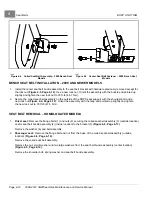
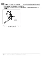
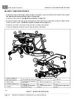
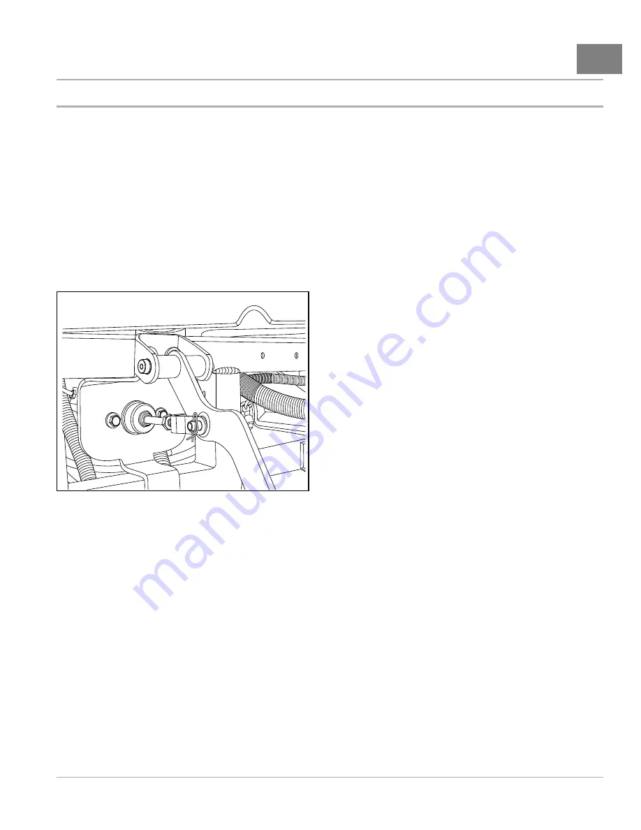
Remove the rue pin and the clevis pin. Separate the clevis from the brake pedal
.
4.
Remove the allen-head shoulder bolt and locknut from the pedal and frame brackets.
5.
Remove the brake pedal.
6.
Inspect the brake pedal bushing for wear and replace if necessary.
1888
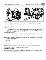
Figure 5-7
Clevis and Rue Pin
BRAKE PEDAL INSTALLATION
1.
Position the brake pedal between the frame brackets.
2.
Install the allen-head shoulder bolt and locknut. Tighten the hardware to 4.8 ft-lb (6.5 N·m).
3.
Install the master cylinder rod and threaded clevis pin assembly.
4.
Install the clevis pin and the rue pin.
5.
Connect battery.
See Connecting the Battery – Gasoline/Diesel Vehicles, Section 1, Page 1-4.
BRAKE PEDAL ADJUSTMENT
1.
Loosen the master cylinder rod and clevis jam nut
2.
Rotate the master cylinder rod to extend or retract the clevis and brake pedal to the desired position.
3.
Tighten the jam nut to 14 ft-lb (19 N·m).
4.
Perform all brake system inspections to ensure that the hydraulic brake system and the park brake system are
adjusted and operating correctly before the vehicle is returned to service.
2008-2012 All-Wheel Drive Maintenance and Service Manual
Page 5-5
Summary of Contents for Carryall 295 SE
Page 2: ......
Page 20: ......
Page 28: ......
Page 58: ......
Page 66: ......
Page 100: ......
Page 122: ......
Page 150: ......
Page 157: ......
Page 190: ......
Page 197: ......
Page 236: ......
Page 284: ......
Page 386: ......
Page 394: ......
Page 442: ......
Page 452: ......
Page 454: ......
Page 455: ......
Page 456: ......

