HYDRAULIC AND PARK BRAKE SYSTEMS
Park Brake System
6
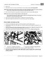
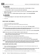
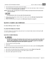
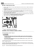
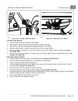
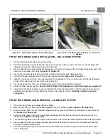
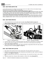
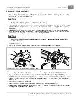
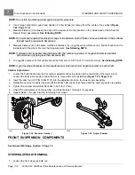
Figure 6-27
Park Brake Equalizer – Bell Crank System
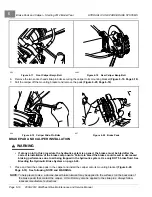
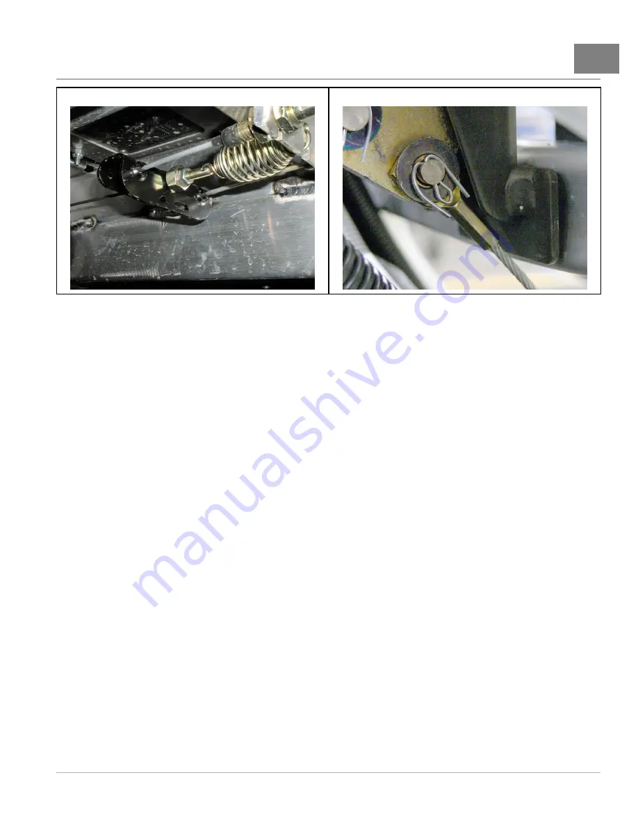
Figure 6-28
Park Brake Cable Attachment – Bell Crank
System
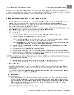
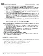
FRONT PARK BRAKE CABLE INSTALLATION – BELL CRANK SYSTEM
1.
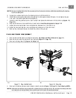
Position the front park brake cable to the vehicle.
2.
Hold the plastic splash panel forward to access and route the cable end up to the lower-most park brake bell
crank and secure the cable ferrule to the frame bracket.
3.
Reach under the driver side instrument panel and use a cotter pin to secure the front park brake cable end to the
lower-most park brake bell crank
4.
Secure the rear cable ferrule to the rear frame bracket nearest the park brake equalizer.
5.
Insert the threaded adjustment rod through the equalizer bracket
6.
Install the conical nut with the cone oriented toward the equalizer and then install a jam nut onto the threaded
portion of the cable end. Advance both nuts a few turns.
7.
Secure the spring from the end of the adjustment rod to the brake cable frame bracket.
8.
Adjust the brake cable equalizer.
See Front Park Brake Cable Adjustment – Bell Crank System on page 6-27.
9.
Inspect all of the brake systems to ensure that both the hydraulic brake system and the park brake system are
adjusted and operating correctly before the vehicle is returned to service.
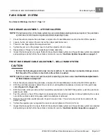
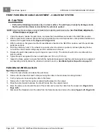
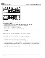
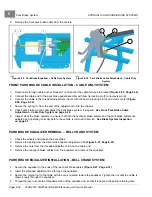
FRONT PARK BRAKE CABLE REMOVAL – CABLE ONLY SYSTEM
1.
Chock the rear wheels and release the park brake.
2.
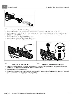
Remove the spring (1) from the threaded adjustment rod (2) at the equalizer
.
3.
Disconnect the cable from the threaded adjustment rod by removing the bow tie locking pin (3) and clevis pin
(4)
4.
Disconnect the cable end from the park brake pedal assembly by removing the bow tie locking pin (5) and
clevis pin (6)
.
5.
Turn the steering wheel fully to the right to allow access in the wheel well area behind the driver side front wheel.
6.
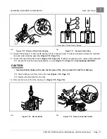
Reach under the driver side wheel well area behind the front wheel and remove the outboard hex-head bolt
securing the plastic splash panel.
7.
Hold the plastic splash panel forward to access and release the tines securing the cable ferrule to the cable
anchor bracket (7).
2008-2012 All-Wheel Drive Maintenance and Service Manual
Page 6-31
Summary of Contents for Carryall 295 SE
Page 2: ......
Page 20: ......
Page 28: ......
Page 58: ......
Page 66: ......
Page 100: ......
Page 122: ......
Page 150: ......
Page 157: ......
Page 190: ......
Page 197: ......
Page 236: ......
Page 284: ......
Page 386: ......
Page 394: ......
Page 442: ......
Page 452: ......
Page 454: ......
Page 455: ......
Page 456: ......

