


ELECTRIC VEHICLE - MOTOR
Reconditioning the Motor
16
RECONDITIONING THE MOTOR
See General Warnings on page 1-1.
Motor reconditioning must be performed by a qualified motor repair technician. The use of proper tools and procedures
is absolutely essential for successful motor reconditioning.
MOTOR SPECIFICATIONS
Any rework must be performed by a qualified technician. Motor service specifications are listed in the following table.
_
ITEM
SERVICE LIMIT
Commutator diameter (minimum)
2.80 in. (71.10 mm)
Commutator concentric with armature shaft within
0.003 in. (0.08 mm)
Bar to bar runout should not exceed
0.005 in. (0.013 mm)
Undercut of segment insulator after machining commutator
0.040 in. (1.0 mm)
Armature resistance at 75 °F (24 °C)
0.012 ohms between bar 1 and bar 15
Field coil resistance at 75 °F (24 °C)
1.75 ohms
MOTOR ASSEMBLY
See General Warnings on page 1-1.
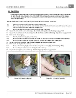
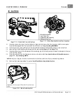
1.
Replace the bearing.
1.1.
Use an arbor press to install a new bearing into the end cap. To help avoid damaging the bearing, apply
pressure only to the outer race when installing the bearing.
1.2.
Install the retaining ring to secure the bearing
2.
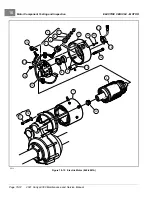
Install the brushes and brush rigging.
See following NOTE.
NOTE:
When installing new brushes, remove and replace brushes one at a time. This method ensures the terminals
and brushes will be properly positioned in the rigging.
When replacing brushes, replace all four brushes. Never replace only two.
Install the brushes in the same rigging 180° apart from each other.
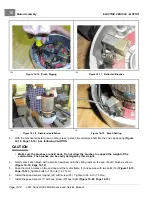
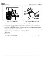
2.1.
Insert the brushes into the brush rigging as shown
.
2.2.
Insert the two terminal posts through insulators (4) in the end cap (11) wall at the A1 and A2 positions
.
2.3.
Place external insulators (5) and washers (6) on each terminal post, and secure terminal with nuts (7).
Tighten nuts (7) to 100 in·lb (11.3 N·m). Ensure that the terminal posts do not rotate when tightening
the nuts
2.4.
Secure the brush rigging to the end cap with two screws. Tighten the screws to 25 in·lb (2.8 N·m)
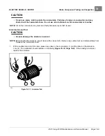
2.5.
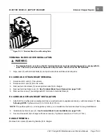
One at a time, push the brushes back until they are completely retracted into their mounting slots and the
spring pressure holds them in the retracted position as shown
.
2021 Carryall 300 Maintenance and Service Manual
Page 16-13
Summary of Contents for Carryall 300 2021
Page 2: ......
Page 16: ......
Page 551: ...80 2018 by Kohler Co All rights reserved KohlerEngines com 17 690 15 Rev...
Page 565: ...GASOLINE ENGINE HARNESS Wiring Diagrams Gasoline Engine Harness 26...
Page 566: ...Page intentionally left blank...
Page 567: ...GASOLINE KEY START MAIN HARNESS Wiring Diagrams Gasoline Key Start Main Harness 26...
Page 568: ...Page intentionally left blank...
Page 569: ...GASOLINE PEDAL START MAIN HARNESS Wiring Diagrams Gasoline Pedal Start Main Harness 26...
Page 570: ...Page intentionally left blank...
Page 571: ...GASOLINE INSTRUMENT PANEL HARNESS Wiring Diagrams Gasoline Instrument Panel Harness 26...
Page 572: ...Page intentionally left blank...
Page 573: ...GASOLINE FNR HARNESS Wiring Diagrams Gasoline FNR Harness 26...
Page 574: ...Page intentionally left blank...
Page 575: ...ELECTRIC MAIN HARNESS Wiring Diagrams Electric Main Harness 26...
Page 576: ...Page intentionally left blank...
Page 577: ...ELECTRIC INSTRUMENT PANEL HARNESS Wiring Diagrams Electric Instrument Panel Harness 26...
Page 578: ...Page intentionally left blank...
Page 579: ...ELECTRIC ACCESSORIES HARNESS Wiring Diagrams Electric Accessories Harness 26...
Page 580: ...Page intentionally left blank...
Page 588: ...NOTES...
Page 589: ...NOTES...
Page 590: ...NOTES...
Page 591: ...NOTES...
Page 592: ...NOTES...
Page 593: ...NOTES...
Page 594: ...NOTES...
Page 595: ......
Page 596: ......