


59
Disassembly/Inspection and Service
17 690 15 Rev. --
KohlerEngines.com
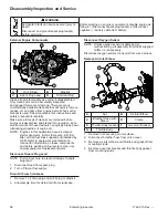
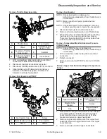
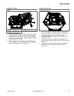
Remove Throttle Body Assembly
D
E
C
B
F
A
G
H
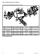
A
Throttle Body
B
Fuel Injector
C
TMAP
D
Throttle Position
Sensor (TPS)
E
Insulator to Throttle
Body Gasket
F
Insulator
G
Insulator to Cylinder
Head Gasket
H
Intake Studs
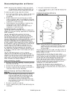
1. With a screwdriver, slide locking tab on electrical
connector of TMAP. Detach connector.
2. Disconnect fuel injector electrical connector.
3. Disconnect throttle position sensor (TPS) connector.
4. Slide throttle body off intake studs and remove
insulator to throttle body gasket, insulator, and
insulator to cylinder head gasket.
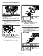
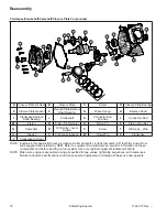
Remove Fuel Injector and TMAP
B
E
C
D
F
A
A
Fuel Injector Cap
B
Screw
C
Metal Retaining Clip
D
Fuel Injector
E
Screw
F
TMAP
Remove Fuel Injector
NOTE: Unless fuel injector is damaged or
malfunctioning, disassembly from throttle body is
unnecessary.
NOTE: Make note of fuel injector position before
removing.
NOTE: Unless fuel injector cap is damaged, removing
retainer securing cap to injector is unnecessary.
1. Disconnect fuel injector electrical connector.
2. Remove screw and pull injector out of throttle body.
3. When removed, pull metal retaining clip connecting
fuel injector to fuel injector cap/fuel cap bracket.
There may be some fuel left in line. Any spilled fuel
must be cleaned up immediately.
Remove Temperature/Manifold Absolute Pressure
(TMAP) Sensor
NOTE: Unless TMAP sensor is damaged or
malfunctioning, disassembly from throttle body is
unnecessary.
1. With a screwdriver, slide locking tab on electrical
connector.
2. Detach connector.
3. Remove screw and pull TMAP sensor out of throttle
body.
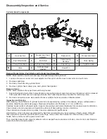
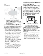
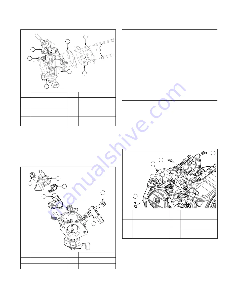
Remove Upper Heat Shield and Engine Temperature
Sensor
F
E
B
D
D
D
A
C
E
A
Upper Heat Shield
B
Engine Temperature
Sensor
C
Dipstick Tube
Bracket
D
Screw
E
Clip
F
Oxygen Sensor
Connector
1. Note position of engine temperature sensor. Sensor
is located between oil fi ll tube bracket and upper
heat shield. Remove screw securing oil fi ll tube
bracket and sensor to upper heat shield.
2. Remove engine temperature wire from upper heat
shield clip. Remove oxygen sensor wire from upper
heat shield clip.
3. Remove screws and lift off upper heat shield.
Summary of Contents for Carryall 300 2021
Page 2: ......
Page 16: ......
Page 551: ...80 2018 by Kohler Co All rights reserved KohlerEngines com 17 690 15 Rev...
Page 565: ...GASOLINE ENGINE HARNESS Wiring Diagrams Gasoline Engine Harness 26...
Page 566: ...Page intentionally left blank...
Page 567: ...GASOLINE KEY START MAIN HARNESS Wiring Diagrams Gasoline Key Start Main Harness 26...
Page 568: ...Page intentionally left blank...
Page 569: ...GASOLINE PEDAL START MAIN HARNESS Wiring Diagrams Gasoline Pedal Start Main Harness 26...
Page 570: ...Page intentionally left blank...
Page 571: ...GASOLINE INSTRUMENT PANEL HARNESS Wiring Diagrams Gasoline Instrument Panel Harness 26...
Page 572: ...Page intentionally left blank...
Page 573: ...GASOLINE FNR HARNESS Wiring Diagrams Gasoline FNR Harness 26...
Page 574: ...Page intentionally left blank...
Page 575: ...ELECTRIC MAIN HARNESS Wiring Diagrams Electric Main Harness 26...
Page 576: ...Page intentionally left blank...
Page 577: ...ELECTRIC INSTRUMENT PANEL HARNESS Wiring Diagrams Electric Instrument Panel Harness 26...
Page 578: ...Page intentionally left blank...
Page 579: ...ELECTRIC ACCESSORIES HARNESS Wiring Diagrams Electric Accessories Harness 26...
Page 580: ...Page intentionally left blank...
Page 588: ...NOTES...
Page 589: ...NOTES...
Page 590: ...NOTES...
Page 591: ...NOTES...
Page 592: ...NOTES...
Page 593: ...NOTES...
Page 594: ...NOTES...
Page 595: ......
Page 596: ......