


76
Reassembly
KohlerEngines.com
17 690 15 Rev. --
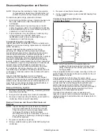
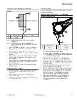
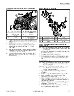
Install Crankshaft Position Sensor
NOTE: Ensure all parts are clean, undamaged and free
of debris and make sure electrical connectors
have seal in place.
NOTE: When mounting ground wire on bottom screw of
bracket, ensure ground wire is routed outside
and away from fl ywheel.
1. Install crankshaft position sensor to bracket. Torque
screw to 4.2 N·m (37 in. lb.).
2. Install crankshaft position sensor and bracket
assembly to crankcase posts.
3. Secure bracket assembly to crankcase posts.
Torque bracket screws to 7.3 N·m (65 in. lb.).
4. Push electrical connector on crankshaft position
sensor making sure a good connection is made.
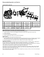
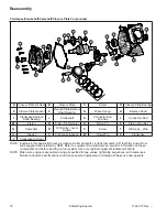
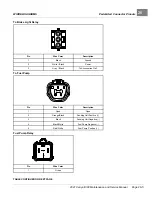
Blower Housing Components
C
E
A
B
D
A
Blower Housing
Screen
B
Screw
C
Screw
D
Blower Housing
E
Clamp
Install Blower Housing
Install blower housing on crankcase with screws. Torque
screws to 10 N·m (89 in. lb.).
Install Blower Housing Screen
Install blower housing screen on blower housing using
screws. Torque screws to 7.3 N·m (65 in. lb.).
Install Wiring Harness Clamp
Insert wiring harness into clamp and install clamp
with wiring harness to blower housing. Tighten screw
securely.
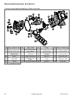
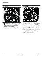
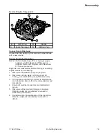
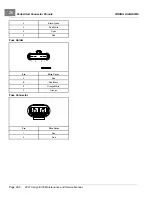
Install Cylinder Shield
A
C
D
B
A
Ground Stud
B
Screw
C
Cylinder Shield
D
Cylinder Head
1. Install cylinder shield on cylinder head; secure with
ground stud and screw as shown. Torque stud and
screw to 8 N·m (71 in. lb.).
2. If removed, install ignition coil onto cylinder shield.
Torque screw to 10.2 N·m (90 in. lb.).
3. Plug connector into ignition coil.
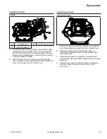
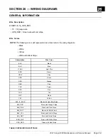
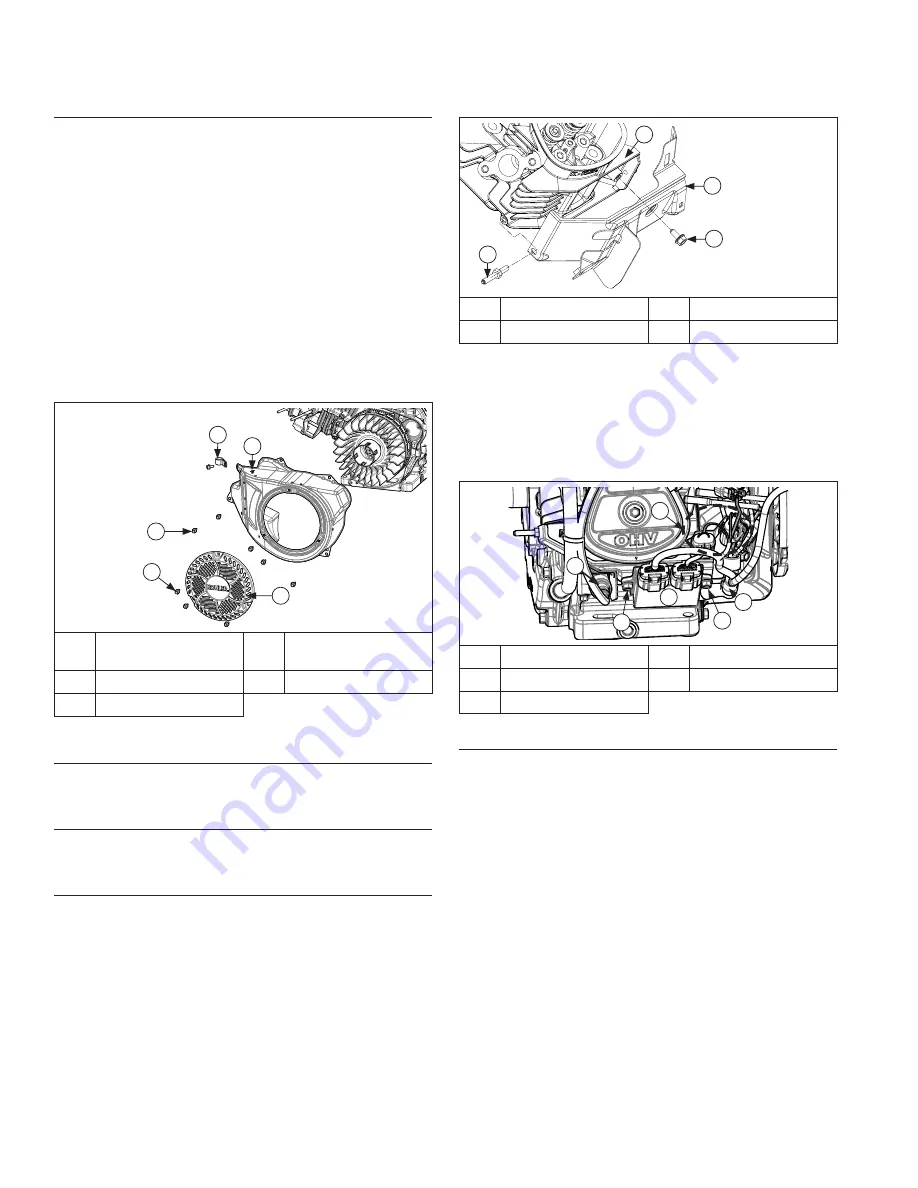
Fuses and ECU Components
C
C
D
E
A
B
A
Fuses/Fuse Holders
B
ECU
C
Screw
D
Cable Clip
E
Ignition Coil
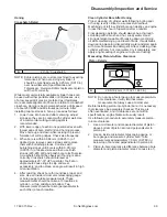
Install Electronic Control Unit (ECU)
NOTE: ECU pins should be coated with a thin layer of
electrical grease to prevent fretting and
corrosion and may need to be reapplied if ECU
is being reused.
1. Connect Black and Grey electrical connectors.
Connectors and ECU are keyed in such a way so
they cannot be installed incorrectly.
2. Install ECU to cylinder shield using screws. Wire
harness clip secures with screw closest to fl ywheel.
Torque screws to 8 N·m (71 in. lb.).
3. Install fuses into holders on cylinder shield.
Summary of Contents for Carryall 300 2021
Page 2: ......
Page 16: ......
Page 551: ...80 2018 by Kohler Co All rights reserved KohlerEngines com 17 690 15 Rev...
Page 565: ...GASOLINE ENGINE HARNESS Wiring Diagrams Gasoline Engine Harness 26...
Page 566: ...Page intentionally left blank...
Page 567: ...GASOLINE KEY START MAIN HARNESS Wiring Diagrams Gasoline Key Start Main Harness 26...
Page 568: ...Page intentionally left blank...
Page 569: ...GASOLINE PEDAL START MAIN HARNESS Wiring Diagrams Gasoline Pedal Start Main Harness 26...
Page 570: ...Page intentionally left blank...
Page 571: ...GASOLINE INSTRUMENT PANEL HARNESS Wiring Diagrams Gasoline Instrument Panel Harness 26...
Page 572: ...Page intentionally left blank...
Page 573: ...GASOLINE FNR HARNESS Wiring Diagrams Gasoline FNR Harness 26...
Page 574: ...Page intentionally left blank...
Page 575: ...ELECTRIC MAIN HARNESS Wiring Diagrams Electric Main Harness 26...
Page 576: ...Page intentionally left blank...
Page 577: ...ELECTRIC INSTRUMENT PANEL HARNESS Wiring Diagrams Electric Instrument Panel Harness 26...
Page 578: ...Page intentionally left blank...
Page 579: ...ELECTRIC ACCESSORIES HARNESS Wiring Diagrams Electric Accessories Harness 26...
Page 580: ...Page intentionally left blank...
Page 588: ...NOTES...
Page 589: ...NOTES...
Page 590: ...NOTES...
Page 591: ...NOTES...
Page 592: ...NOTES...
Page 593: ...NOTES...
Page 594: ...NOTES...
Page 595: ......
Page 596: ......