13
Speed Controller
ELECTRIC VEHICLE - ELECTRICAL
COMPONENTS
2
S
1
S
–
M
+
B
–
B
2
S
1
S
1
1
2
3
6
2
2
1
2901
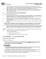
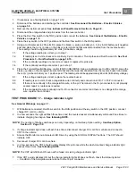
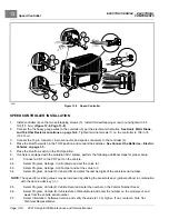
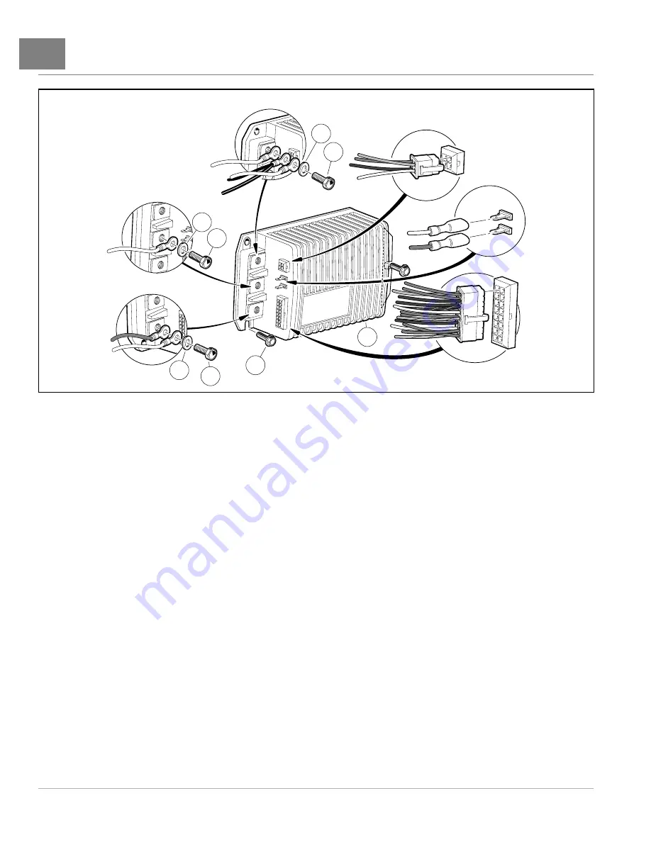
Figure 13-6
Speed Controller
SPEED CONTROLLER INSTALLATION
1.
Install controller (6) on the two self-tapping screws (3). Install third self-tapping screw (3) and tighten to 5.5
ft·lb (7.5 N·m)
2.
Connect the the heavy gauge wires to the controller (6) per the electrical schematics.
and 10k Ohm Resistor Locations on page 12-4.
Tighten terminal screws (1) on the controller to 108 in·lb
(12.2 N·m).
3.
Connect the 16-pin connector, 4-pin connector, and spade connectors to the controller (6).
4.
Place the Run/Tow switch in the TOW position and connect the batteries.
See Connect the Batteries – Electric
5.
Place the Run/Tow switch in the RUN position.
6.
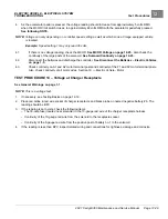
If vehicle is equipped with the Guardian SVC system, perform the following additional steps for proper setup.
6.1.
Connect a CDT to the CDT port on the vehicle.
6.2.
Select
Program, Settings, Control Mode
and set the value to 1.
6.3.
Select
Program, Settings, Anti Tamper
and set the value to 0.
6.4.
Select
Program, Vehicle ID, Vehicle S/N
and enter the last six digits of the vehicle serial number.
NOTE:
The speed for scrolling values may be increased by utilizing the bookmark keys (yellow buttons) in combination
with the data inc/dec key (+/-).
6.5.
Select
Program, Vehicle ID, Vehicle Decal
and enter the number on the Vehicle Number Decal.
6.6.
Select
Program, Vehicle ID, Vehicle Date of Manufacture
and enter the number on the model year and
week from the vehicle serial number.
6.7.
Select
Information, Software Version
and verify the value is 13 or higher. If not, contact a Club Car
Technical Representative.
Page 13-8
2021 Carryall 300 Maintenance and Service Manual
Summary of Contents for Carryall 300 2021
Page 2: ......
Page 16: ......
Page 551: ...80 2018 by Kohler Co All rights reserved KohlerEngines com 17 690 15 Rev...
Page 565: ...GASOLINE ENGINE HARNESS Wiring Diagrams Gasoline Engine Harness 26...
Page 566: ...Page intentionally left blank...
Page 567: ...GASOLINE KEY START MAIN HARNESS Wiring Diagrams Gasoline Key Start Main Harness 26...
Page 568: ...Page intentionally left blank...
Page 569: ...GASOLINE PEDAL START MAIN HARNESS Wiring Diagrams Gasoline Pedal Start Main Harness 26...
Page 570: ...Page intentionally left blank...
Page 571: ...GASOLINE INSTRUMENT PANEL HARNESS Wiring Diagrams Gasoline Instrument Panel Harness 26...
Page 572: ...Page intentionally left blank...
Page 573: ...GASOLINE FNR HARNESS Wiring Diagrams Gasoline FNR Harness 26...
Page 574: ...Page intentionally left blank...
Page 575: ...ELECTRIC MAIN HARNESS Wiring Diagrams Electric Main Harness 26...
Page 576: ...Page intentionally left blank...
Page 577: ...ELECTRIC INSTRUMENT PANEL HARNESS Wiring Diagrams Electric Instrument Panel Harness 26...
Page 578: ...Page intentionally left blank...
Page 579: ...ELECTRIC ACCESSORIES HARNESS Wiring Diagrams Electric Accessories Harness 26...
Page 580: ...Page intentionally left blank...
Page 588: ...NOTES...
Page 589: ...NOTES...
Page 590: ...NOTES...
Page 591: ...NOTES...
Page 592: ...NOTES...
Page 593: ...NOTES...
Page 594: ...NOTES...
Page 595: ......
Page 596: ......

