TROUBLESHOOTING AND ELECTRICAL SYSTEM:
DIESEL VEHICLES
Test Procedures
12
2106
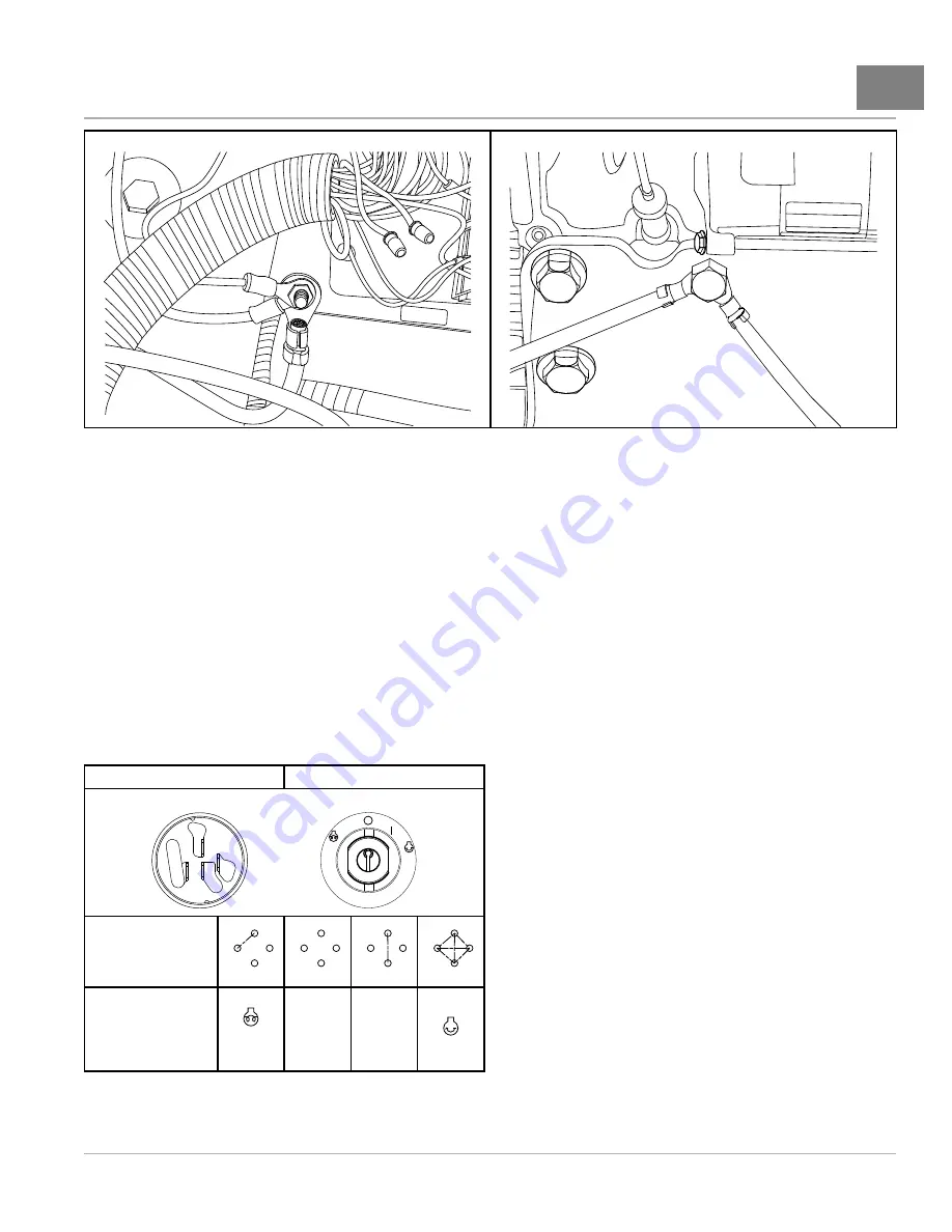
Figure 12-8
Frame Ground
2107
Figure 12-9
Engine Ground (Under Starter)
TEST PROCEDURE 4 – Key Switch (Starter Circuit)
See General Warnings, Section 1, Page 1-2.
1.
Disconnect battery.
See Disconnecting the Battery – Gasoline/Diesel Vehicles, Section 1, Page 1-3.
2.
Remove the key switch.
See Key Switch Removal on page 14-7.
3.
Ensure that the key switch connector is connected correctly and is tight. If it is not, repair or replace as necessary.
4.
Set the multimeter to 200 ohms.
5.
Check the B and A key switch terminals.
5.1. Use alligator clips to connect the multimeter probes between the B and A terminals. With the key switch
in the START position, the multimeter should indicate continuity
. If the
multimeter does not indicate continuity, the key switch has failed and should be replaced.
5.2. If the multimeter indicates continuity between the B and A terminals with the key in any position other than
START, the key switch has failed and should be replaced.
See Key Switch Removal on page 14-7.
REAR VIEW
FRONT VIEW
B
S
I
A
Continuity Diagram
B
S
I
A
B
S
I
A
B
S
I
A
B
S
I
A
Key Position
PRE-
HEAT
O
OFF
I
ON
START
2108
Figure 12-10
Key Switch Terminals and Continuity
Diagram
6.
Check the B and I terminals.
2013 Carryall 295/XRT 1550 Maintenance and Service Manual
Page 12-15
Summary of Contents for Carryall XRT 1550
Page 2: ......
Page 28: ......
Page 40: ......
Page 62: ......
Page 106: ......
Page 120: ......
Page 180: ......
Page 224: ......
Page 272: ......
Page 310: ......
Page 344: ......
Page 362: ......
Page 370: ......
Page 418: ...NOTES...
Page 428: ...NOTES...
Page 430: ...NOTES...
Page 431: ......
Page 432: ......


