STEERING AND FRONT SUSPENSION
Rack and Pinion
7
3.
Slide the universal joint down over the pinion. Align the flat-way on the pinion with the bolt path on the universal
joint.
4.
Install the universal bolt on the pinion shaft and tighten to 18 ft-lb (24 N·m).
See following NOTE.
NOTE:
Be sure to tighten the bolt at the universal joint on the rack and pinion shaft before tightening the steering
column coupling bolt.
5.
Tighten the universal joint bolt on the steering column to 18 ft-lb (24 N·m).
6.
Install both outer drag link ball joints, and advance the bolt approximately 6 threads. Do not tighten the jam
nuts. Jam nuts will be tightened during alignment.
7.
Install the outer drag link ball joints on each upright, and tighten the hardware to 70 ft-lb (95 N·m)
8.
Align the front wheels.
See Wheel Alignment on page 7-10.
9.
Adjust the outer drag link jam nuts, and tighten the hardware to 21 ft-lb (28.4 N·m).
10. Adjust the inner drag link jam nuts, and tighten the hardware to 21 ft-lb (28.4 N·m).
11. Remove the vehicle jack stands, and lower the vehicle to the ground.
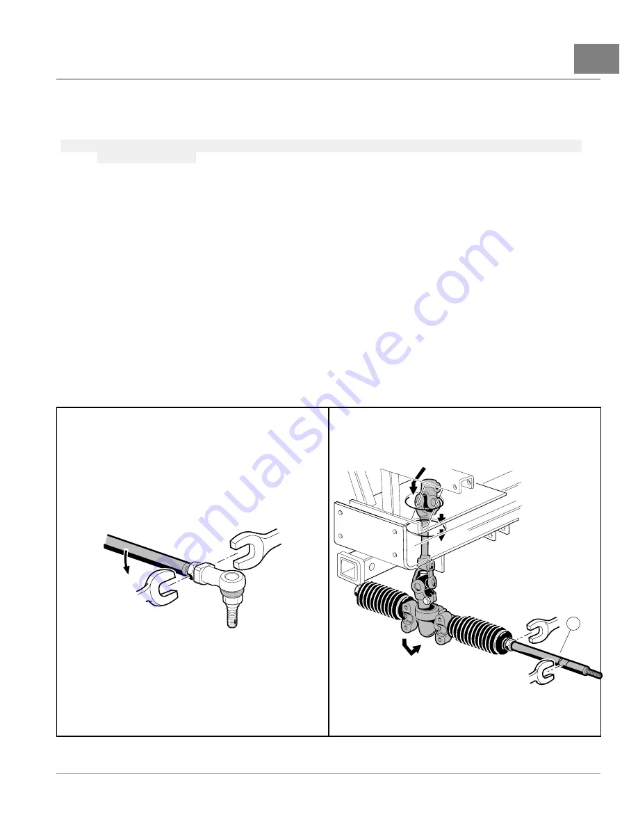
RACK AND PINION DISASSEMBLY
1.
Remove the rack and pinion and drag link assembly.
See Rack and Pinion Removal on page 7-4.
2.
Remove the two outer ball joints from the drag links
3.
Remove both drag links (19)
19
2048
Figure 7-7
Drag Link Ball Joint
2049
Figure 7-8
Drag Link
2013 Carryall 295/XRT 1550 Maintenance and Service Manual
Page 7-5
Summary of Contents for Carryall XRT 1550
Page 2: ......
Page 28: ......
Page 40: ......
Page 62: ......
Page 106: ......
Page 120: ......
Page 180: ......
Page 224: ......
Page 272: ......
Page 310: ......
Page 344: ......
Page 362: ......
Page 370: ......
Page 418: ...NOTES...
Page 428: ...NOTES...
Page 430: ...NOTES...
Page 431: ......
Page 432: ......


