background image

Battery

Page 58

2007 Carryall 295 Intellitach and XRT 1550 Intellitach Diesel Vehicle Owner’s Manual

BATTERY

See General Warnings on page 8.

ý 

DANGER

• Battery – Explosive gases! Do not smoke. Keep sparks and flames away from the vehicle and

service area. Ventilate when charging or operating vehicle in an enclosed area. Wear a full
face shield and rubber gloves when working on or near batteries.

• Battery – Poison! Contains acid! Causes severe burns. Avoid contact with skin, eyes, or

clothing. Antidotes:

- External: Flush with water. Call a physician immediately.

- Internal: Drink large quantities of milk or water followed with milk of magnesia or vegetable

oil. Call a physician immediately.

- Eyes: Flush with water for 15 minutes. Call a physician immediately.

• Tools, wires, and metal objects can cause sparks when shorted across a battery.

ý 

WARNING

• Wear safety glasses or approved eye protection when servicing the vehicle. 

• Follow all instructions carefully when working with batteries.

• When jumping from a booster battery make final (negative) connection at engine frame.

• Do not jump start or charge a frozen or damaged battery. Unplug charger before connecting

or disconnecting cables to the battery. Never lean over battery while boosting, testing, or
charging.

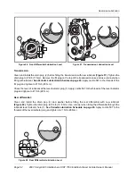
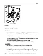
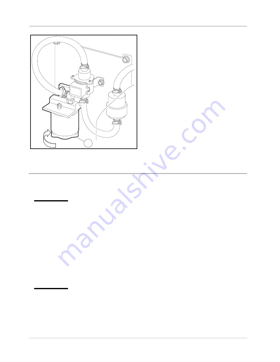
Figure 63   Fuel Filter

1

Summary of Contents for IntelliTach Carryall 295

Page 1: ...Owner s Manual 2007 IntelliTach All Wheel Drive Vehicles Diesel Carryall 295 XRT 1550...

Page 2: ......

Page 3: ...or for incidental or consequential damages that result from the use of the material in this manual This manual contains proprietary information that is protected by copyright All rights are reserved...

Page 4: ...ers we recommend that you ask them to read this manual before they operate the vehicle Club Car products are backed by a customer support system designed to offer you fast courteous service In the eve...

Page 5: ...ructions 22 Bed Latch and Prop Rod 25 Attachments and Buckets 27 Loading and Unloading the Cargo Bed 37 Vehicle Load Capacities 37 Towing with the Vehicle 39 Transporting on a Trailer 39 Storage 40 Ma...

Page 6: ...DECAL ON PASSENGER SIDE SEAT SUPPORT HOT MANIFOLD WARNING DECAL ON ENGINE VALVE COVER ROTATING PARTS AND HOT MANIFOLD DECAL ON DRIVER SIDE VEHICLE FRAME FRAME GROUND WARNING DECAL ON VEHICLE FRAME NE...

Page 7: ...s HIGH PRESSURE FLUIDS COULD CAUSE SERIOUS INJURY OR DEATH Do not modify or remove Roll over Protective Structure ROPS Replace ROPS if damaged Do not attempt repair Use seat belts during operation Do...

Page 8: ...Page 6 2007 Carryall 295 IntelliTach and XRT 1550 IntelliTach Diesel Vehicle Owner s Manual...

Page 9: ...ssential and must be followed If any of the operation or warning decals on the vehicle become damaged have been removed or cannot be easily read they should be replaced immediately to avoid possible p...

Page 10: ...tate and local laws pertaining to child safety The driver and passenger must be restrained at all times with the safety belts provided to help prevent injury in the event of sudden braking collision o...

Page 11: ...gine or any other metal component Wear safety glasses or approved eye protection when servicing the vehicle Wear a full face shield and rubber gloves when working on or near batteries Do not wear loos...

Page 12: ...neral Warnings on page 8 WARNING Before allowing anyone to drive the vehicle make sure the driver is familiar with all controls and operating procedures Do not tamper with the high idle speed setting...

Page 13: ...verse Handle 9 Park Brake Release Handle A Move up for FORWARD travel 10 Headlight Switch B NEUTRAL Position 11 High Temperature Warning light C Move down for REVERSE travel 12 Safety Belt Warning lig...

Page 14: ...l is pressed Shift the handle only when the vehicle is at a complete stop and the engine is at idle Failure to heed this caution could result in damage to the transmission NOTE The key can be removed...

Page 15: ...position Figure 4 While holding the steering wheel in the desired position pull up on the steering adjust ment lock lever to firmly lock the steering column in position WARNING Ensure that the steerin...

Page 16: ...ice Schedule on page 42 HEADLIGHT CONTROL The headlight control 10 is located on the left side of the instrument panel Figure 4 Press the headlight rocker switch to turn the headlights on or off NOTE...

Page 17: ...6 and Figure 7 controls the hydraulic cylinders for the lift and tilt func tions See following NOTE NOTE The joystick will not activate the attachment arm unless the start key is ON and the joystick...

Page 18: ...ated Tilt Operation 1 Move the joystick 1 to the right 5 to tilt the bucket forward Figure 7 2 Move the joystick 1 to the left 6 to tilt the bucket back Front Auxiliary Hydraulics Operation If Equippe...

Page 19: ...g vehicle and attachments Be careful when connecting and disconnecting quick couplers Relieve Hydraulic Pressure Hydraulic pressure in the auxiliary circuit can make it difficult to connect or disconn...

Page 20: ...heck for kinks or twists Then make sure it remains free of twists as it retracts Figure 10 WARNING Do not operate the vehicle with the ROPS removed Doing so could result in property damage personal in...

Page 21: ...ing a child safety seat must not ride on the vehicle Comply with state and local laws pertaining to child safety CAUTION Be careful not to damage the safety belt webbing or hardware Inspect the safety...

Page 22: ...seat back and pull firmly in a forward upward direction until the latch releases To engage the seat latch push down firmly on the seat back until the seat locks into place See following WARNING WARNIN...

Page 23: ...nd Safety Belts on page 17 Safety belts Visually inspect for cuts fraying and loose parts See Roll Over Protective Structure ROPS and Safety Belts on page 17 Tires Check for proper tire pressure Visua...

Page 24: ...The reverse buzzer should sound as a warning when the Forward Reverse handle is in the REVERSE position Steering The vehicle should be easy to steer and should not have any play in the steering wheel...

Page 25: ...on slopes exceeding 20 incline Avoid stopping a loaded vehicle on a hill If a loaded vehicle must be stopped on a hill avoid sudden starts or rolling backwards and stopping suddenly Failure to heed t...

Page 26: ...dle in desired posi tion Figure 4 Page 11 Engine must be at idle before moving shift handle A buzzer will sound as a warning when the Forward Reverse handle is in the REVERSE position 13 Release the b...

Page 27: ...ent this condition avoid extremely hard braking in reverse STOPPING THE VEHICLE To stop the vehicle release the accelerator pedal and press the brake pedal until the vehicle comes to a com plete stop...

Page 28: ...ure Otherwise the bed will fall resulting in severe personal injury or death WARNING For vehicles with cargo beds remove all cargo before raising the bed or servicing the vehicle If the vehicle is equ...

Page 29: ...terial is loaded the volume must be reduced See Attachment Arm Rated Capacity on page 38 Exceeding the attachment arm rated capacity can cause the following problems Figure 14 Steering may be difficul...

Page 30: ...sengage the park brake 4 Press the joystick ON OFF rocker switch 18 to ON Figure 4 5 Lower the attachment arm and tilt the attachment interface forward 6 Drive forward until the front edge of the atta...

Page 31: ...ucket or attachment to the attachment interface Figure 20 WARNING Attachment interface pins must extend through the holes in attachment with lever in the locked position Failure to secure pins can all...

Page 32: ...ols until the vehicle can be handled at an efficient and safe rate for all conditions of the work area NOTE Always warm up the engine before operating the vehicle with an attachment If movement of the...

Page 33: ...end toward the top of the slope Figure 25 Operating with an Empty Bucket and Loaded Cargo Box 1 Raise the bucket only high enough to avoid obstructions on rough ground 2 With empty bucket and a loade...

Page 34: ...position is for the mower blade or broom attachments To level the ground using float the ground must contain loose debris 1 Raise the attachment arm B and tilt the bucket forward D Figure 29 2 Push th...

Page 35: ...pting to remove the attachment arm mecha nism from the vehicle Removing the Attachment Arm NOTE When removing the cylinders from the attachment arm or the interface the cylinders may need to be retrac...

Page 36: ...ure 35 10 Install the existing pin 3 and retaining ring to secure the cylinder to the mount 11 Rotate the attachment interface cylinder 5 upward against the vehicle and snap it into place 8 12 Install...

Page 37: ...oth sides Figure 37 4 Raise the attachment arms and align the holes in the attachment arms to the vehicle mounting holes Figure 39 5 Install the pins 2 and retaining rings 1 both sides WARNING Do not...

Page 38: ...rs to the attachment arm and interface during installation the cylinders may need to be retracted slightly to relieve the hydraulic pressure Do not have hands in the area of the cylinders when extendi...

Page 39: ...a hill when loaded If you must stop on a hill avoid sudden starts or rolling backwards and stopping suddenly Failure to heed this warning may cause vehicle to overturn possibly resulting in severe pe...

Page 40: ...attachment arm and weight of the attachment s contents If other attachments such as Pallet Forks are used the attachment arm capacity is reduced as the load center is moved forward Attachment Arm Rat...

Page 41: ...G Do not allow riders in the trailer being towed Avoid sudden starts sudden stops and tight turns when towing Avoid stopping on a hill when towing If you must stop on a hill avoid sudden starts or rol...

Page 42: ...by a trained technician Use an automotive type 12 volt battery charger rated at 10 amps or less Check electrolyte level after charging and add distilled water if necessary 3 Make sure the key switch...

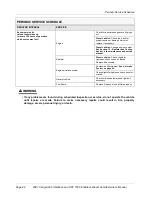
Page 43: ...aintenance can prevent vehicle downtime and expensive repairs Use the Pre Operation and Daily Safety Checklist on page 21 and the following Periodic Service Schedule and Periodic Lubrication Schedule...

Page 44: ...lieve pressure before disconnecting hydraulic lines or fittings If wires are removed or replaced make sure wiring and wire harness are properly routed and secured Failure to properly route and secure...

Page 45: ...vehicles Check for grass and debris around the radiator Tires Check air pressure and adjust if necessary See Vehicle Specifications on page 63 Transmission and differentials Check lubricant levels Ad...

Page 46: ...for leaks around gaskets fill plugs etc Diesel vehicles Check the v belt for proper tension or damage Adjust or replace if necessary Diesel vehicles Change engine coolant See Section 15 Radiator and C...

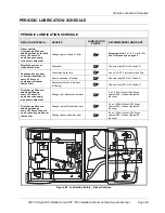
Page 47: ...of operation whichever comes first Check add brake fluid Use only DOT 5 silicone brake fluid Rear suspension 2 fittings Chassis Lube EP NLGI Grade 2 Attachment Arm and Interface 8 fittings Chassis Lu...

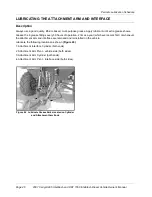
Page 48: ...ease the 8 grease fittings every 50 hours of operation 2 times a year whichever occurs first or whenever the attachment arm and interface are removed and reinstalled on the vehicle Lubricate the follo...

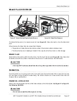
Page 49: ...should be clean with no residue in the bottom of the reservoir or other evidence of contamination CAUTION Use only DOT 5 silicone brake fluid Use of any other type brake fluid is not recommended ENGIN...

Page 50: ...Forward Reverse handle in the NEUTRAL position Chock the front wheels 2 Disconnect the battery cables negative cable first See WARNING To avoid unintentionally start ing on page 10 3 Remove the oil f...

Page 51: ...val Position the port of the plastic container so oil will be directed into the oil pan Figure 52 A drip guard can be made by folding a piece of card board thin metal or plastic under the oil filter f...

Page 52: ...attery Terminal Protector Spray CCI P N 1014305 3 With the Forward Reverse handle in the NEUTRAL position start and run the engine for a few minutes Observe both the drain plug and the oil filter from...

Page 53: ...dicator hole upper plug 1 as a lubricant level indicator Lubricant level should be even with the bottom of level indicator hole 1 LUBRICATION CHANGE FOR FRONT DIFFERENTIAL TRANSMISSION AND REAR DIFFER...

Page 54: ...heck the level of lubricant at the level indicator plug 1 Apply Loctite 567 to the threads of the level indicator plug and tighten to 21 ft lb 28 N m Rear differential Clean and install the drain plug...

Page 55: ...tion but DO NOT start the engine 3 Press the joystick ON OFF switch 18 to ON Figure 4 4 Move the joystick 1 back and raise the attachment arm fully Figure 59 5 Move the joystick 1 to the right and til...

Page 56: ...rve tank is pressurized Do not remove cap when engine is hot AIR INTAKE SYSTEM CAUTION Do not drill into the driver side frame Failure to heed this caution could damage the engine by allowing excessiv...

Page 57: ...General Warnings on page 8 DANGER Turn key switch to the OFF position before fueling Never pour fuel into the fuel tank when the engine is hot or while it is running To avoid electric arc caused by s...

Page 58: ...elp prevent damage to painted surfaces If Biodiesel fuel will be used in the Kubota D722 engine be sure that it meets the following requirements The fuel mixture can include no more than 5 Biodiesel f...

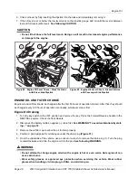
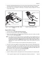
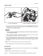
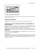
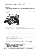
Page 59: ...rom the fuel filter daily The fuel filter is mounted on a plate by the lower seat support panel Figure 63 1 Position a pan under the fuel filter 2 Lift the passenger side seat 3 Locate the valve 1 on...

Page 60: ...ician immediately Internal Drink large quantities of milk or water followed with milk of magnesia or vegetable oil Call a physician immediately Eyes Flush with water for 15 minutes Call a physician im...

Page 61: ...ve designated fill line Replace battery cell caps 6 Clean both battery terminals with a solution of baking soda and water 1 cup 237 mL baking soda per 1 gallon 3 8 L of water Rinse thoroughly Do not a...

Page 62: ...ss the engine compartment by lifting the cargo bed up See WARNING For vehicles with cargo beds on page 8 4 Locate the vehicle battery on the driver s side of the vehicle under the cargo bed Do not rem...

Page 63: ...ervice manual See following NOTE NOTE Dispose of waste water properly ACCESSORIES There is a complete line of accessory equipment available from Club Car and our dealers distributors You can obtain th...

Page 64: ...ll significantly decrease the life of the mud tires Vehicle performance will also be reduced when driv ing on paved surfaces See following WARNING WARNING To avoid the risk of rollover when operating...

Page 65: ...rack and pinion Ackerman Brakes Hydraulic brake system brake pads and discs on each wheel with separate foot operated park brake BODY CHASSIS Frame Chassis Box tube aluminum Side and rear body Plasti...

Page 66: ...Standard seating capacity 2 LIQUID CAPACITIES Engine crankcase with filter SAE 10W 30 API classification CF 3 qt 2 8 L Front differential Mobil 424 Exxon Hydraul 560 or Esso Hydraul 56 lubricant 5 oz...

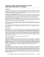
Page 67: ...s such as the charger plug and receptacle brake shoes belts brushes bushings engine mounts mats and pads maintenance adjustments cosmetic deterioration and items which deteriorate or fail due to expos...

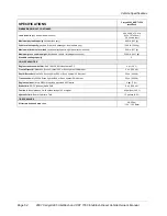
Page 68: ...TION OR WARRANTY OF ANY KIND AND NO REPRESENTATIVE EMPLOYEE OR DEALER OF CLUB CAR HAS THE AUTHORITY TO MAKE OR IMPLY ANY REPRESENTATION PROMISE OR AGREEMENT WHICH IN ANY WAY VARIES THE TERMS OF THIS W...

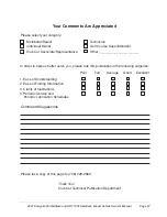
Page 69: ...Information 3 Clarity of Illustrations 4 Periodic Service and Periodic Lubrication Schedules Poor Fair Average Good Excellent Comments Suggestions In order to help us better serve you please rate this...

Page 70: ......

Page 71: ......

Page 72: ...Car Inc P O Box 204658 Augusta GA 30917 4658 USA Web www clubcar com Phone 1 706 863 3000 1 800 ClubCar Intl l 1 706 863 3000 Fax 1 706 863 5808 Publication Part Number 103218304 Edition Code 0606B03...

Reviews: