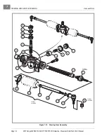


STEERING AND FRONT SUSPENSION
Front Suspension Components
Page 7-14
2007 Carryall 295/295 SE & XRT 1550/1550 SE Gasoline, Diesel and IntelliTach M & S Manual
7
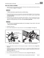
Steering Upright Removal, Continued:
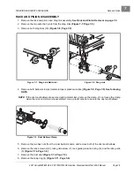
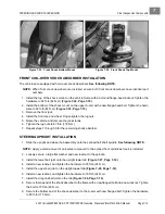
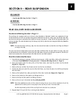
7. Remove the drag link ball joint from the upright assembly
(Figure 7-26, Page 7-14)
.
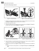
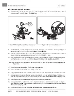
8. Remove the axle spindle locknut that secures the wheel hub, disc, and upright.
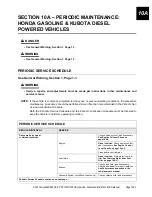
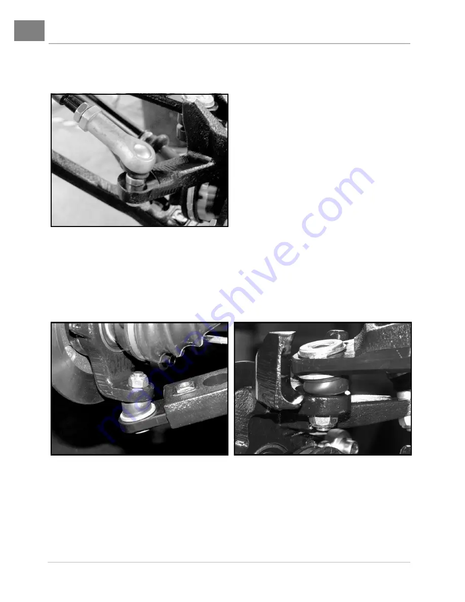
9. Remove the lower and upper ball joint locknut.
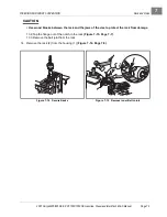
10. Swing the lower A-arm down, and separate the brake rotor and upright from the half-shaft and the upper
ball joint.
11. Repeat steps 5 through 10 for the remaining front wheel if necessary.
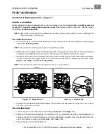
UPPER A-ARM REMOVAL
1. Chock the rear wheels, set the park brake, loosen the front wheel lug nuts, and lift the front of the vehicle
with a chain hoist or floor jack.
See WARNING “Lift only one end...” in General Warning, Section 1,
Page 1-2
.
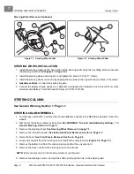
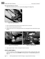
Figure 7-26 Drag Link Ball Joint
Figure 7-27 Lower Ball Joint
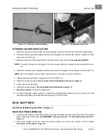
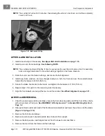
Figure 7-28 Upper Ball Joint
Summary of Contents for IntelliTach XRT 1550
Page 2: ......
Page 22: ...1...
Page 54: ...4...
Page 60: ...5...
Page 90: ...6...
Page 114: ...8...
Page 118: ...9...
Page 196: ...11A...
Page 290: ...11C...
Page 468: ...13C...
Page 490: ...14...
Page 498: ...15...
Page 548: ...16...
Page 560: ...Club Car R NOTES...
Page 561: ...Club Car R NOTES...
Page 562: ...Club Car R NOTES...
Page 563: ......