
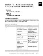
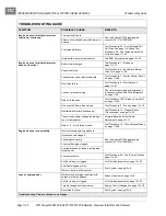
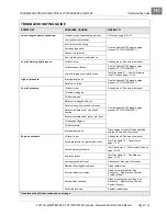
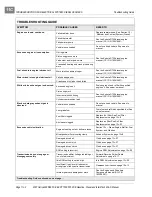
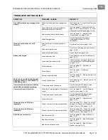

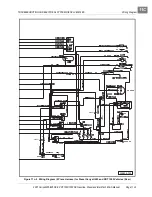
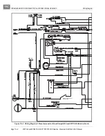

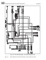


TROUBLESHOOTING AND ELECTRICAL SYSTEM: DIESEL VEHICLES
Test Procedures
Page 11c-12
2007 Carryall 295/295 SE & XRT 1550/1550 SE Gasoline, Diesel and IntelliTach M & S Manual
11C
TEST PROCEDURES
INDEX OF TEST PROCEDURES
1. Battery
2. Fuse
3. Ground Cables
4. Key Switch (Starter Circuit)
5. Key Switch (ON Position)
6. Key Switch (Glow Plug Circuit)
7. Starter Control Circuit
8. Start Relay
9. Differential Relay
10. Fan Relay
11. Thermostat Switch
12. Fan Motor
13. Wire Harness Diodes
14. Neutral Switch (Transmission)
15. Wire Continuity
16. Front Differential Limit Switch
17. Front Drive Gearcase Coil
18. Alternator
19. 60-Amp Fusible Link
20. Coolant Temperature Warning Light Circuit
21. Glow Plug Circuit
22. Reverse Warning Buzzer Limit Switch (If Equipped)
23. Reverse Warning Buzzer (If Equipped)
24. Fuel Solenoid Pull Coil Circuit
25. Fuel Solenoid Hold Coil Circuit
26. Fuel Pump Circuit
27. Low Oil Warning Light Circuit
28. 12-Volt Accessory Receptacle
29. Fuel Level Sending Unit
30. Fuel Gauge
31. Hour Meter
32. Light Switch
33. Voltage at Headlight Socket
34. Bed Lift Motor
35. Bed Lift Switch
36. Bed Lift Circuit Breaker
Summary of Contents for IntelliTach XRT 1550
Page 2: ......
Page 22: ...1...
Page 54: ...4...
Page 60: ...5...
Page 90: ...6...
Page 114: ...8...
Page 118: ...9...
Page 196: ...11A...
Page 290: ...11C...
Page 468: ...13C...
Page 490: ...14...
Page 498: ...15...
Page 548: ...16...
Page 560: ...Club Car R NOTES...
Page 561: ...Club Car R NOTES...
Page 562: ...Club Car R NOTES...
Page 563: ......