

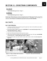


DRIVETRAIN COMPONENTS
Rear Receiver Hitch
2007 Carryall 295/295 SE & XRT 1550/1550 SE Gasoline, Diesel and IntelliTach M & S Manual
Page 14-7
14
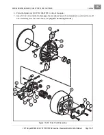
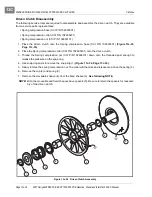
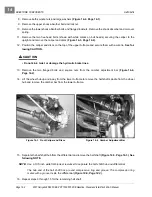
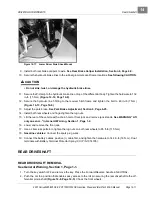
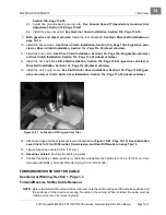
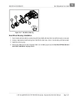
4. Slide the front driveshaft toward the transmission until the universal joint clears the front differential pin-
ion shaft.
5. Slide the driveshaft off the transmission, through the oval-shaped frame shield, and remove from vehicle.
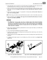
FRONT DRIVESHAFT INSTALLATION
See General Warning, Section 1, Page 1-1.
1. Apply a light coat of anti-seize compound to the differential pinion shaft and splined shaft of transmission.
2. Slide the front driveshaft through the oval-shaped frame shield and onto the splined shaft of the trans-
mission.
3. Slide the front differential pinion shaft into the universal joint so the roll pin holes in the driveshaft and dif-
ferential pinion shaft are aligned.
4. Secure the differential plate to the frame support weldments with new flange-head bolts. Tighten the
hardware to 23 ft-lb (31 N·m)
(Figure 14-11, Page 14-5)
.
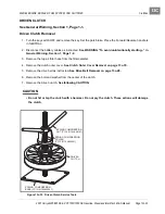
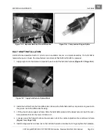
5. Drive a new roll pin into the differential pinion shaft and driveshaft universal joint coupling.
See following
NOTE.
NOTE:
The roll pin should be slightly below the surface on both sides of the coupling.
Use a 1/4-inch roll pin punch to drive the roll pin into place.
6. Connect the battery cables, positive (+) cable first, and tighten the hardware to 144 in-lb (16 N·m). Coat
terminals with Battery Terminal Protector Spray (CCI P/N 1014305).
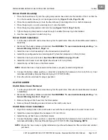
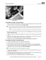
REAR RECEIVER HITCH
REAR RECEIVER HITCH REMOVAL
See General Warning, Section 1, Page 1-1.
1. Turn the key switch OFF and remove the key. Set the park brake. Place the Forward/Reverse handle in
NEUTRAL. Chock the rear wheels.
2. Disconnect the battery cables as instructed.
See WARNING “To avoid unintentionally starting...” in
General Warning, Section 1, Page 1-2.
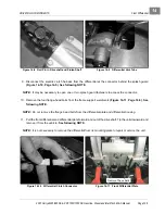
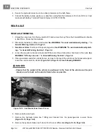
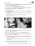
3. Remove the hydraulic line T-bracket from the passenger side of the receiver hitch.
4. Remove the hydraulic line from the rubber grommets and hitch frame.
5. Remove the four bolts, washers, and flanged locknuts from the receiver hitch frame and swing arm
mounting plates and remove the receiver hitch.
REAR RECEIVER HITCH INSTALLATION
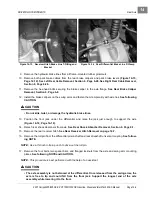
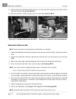
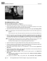
1. Position the receiver hitch onto the swing arm mounting plates and mounting holes.
2. Secure the receiver hitch with new bolts, flat washers, and new flanged locknuts. Tighten the hardware
to 82 ft-lb (111 N·m).
3. Secure the hydraulic brake line T-fitting and tighten the hardware to 48 in-lb (7 N·m)
(Figure 14-13,
Page 14-9)
.
Summary of Contents for IntelliTach XRT 1550
Page 2: ......
Page 22: ...1...
Page 54: ...4...
Page 60: ...5...
Page 90: ...6...
Page 114: ...8...
Page 118: ...9...
Page 196: ...11A...
Page 290: ...11C...
Page 468: ...13C...
Page 490: ...14...
Page 498: ...15...
Page 548: ...16...
Page 560: ...Club Car R NOTES...
Page 561: ...Club Car R NOTES...
Page 562: ...Club Car R NOTES...
Page 563: ......