UNITIZED TRANSAXLE
Unitized Transaxle Assembly
Page 16-34 2001 Pioneer 900 Gasoline Vehicle Maintenance and Service Manual
16
IUnitized Transaxle Assembly, Continued:
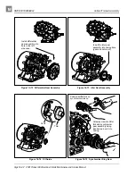
11.7. install the left (driver side) axle shaft (67) in the left axle tube (75) (Figure 16-5, Page 16-4). Using
90° angle (.090 tip) snap ring pliers, install the retaining ring as shown (Figure 16-83, Page 16-35).
11.8. Place a 1/4 to 3/8 inch (6-10 mm) diameter rod against the retaining ring and tap lightly at four to
five locations to ensure it is properly seated. See preceding WARNING.
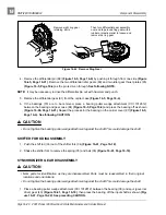
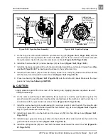
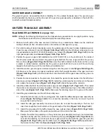
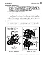
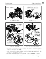
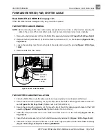
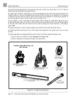
Figure 16-78 Gear Alignment
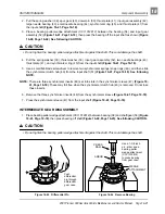
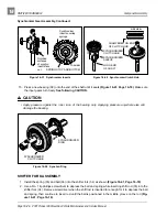
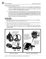
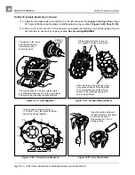
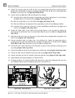
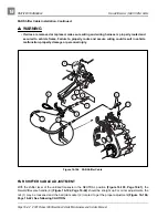
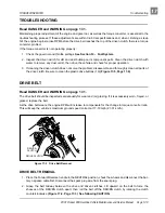
Figure 16-79 Prepare Mating Surfaces
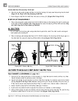
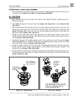
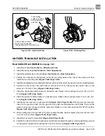
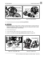
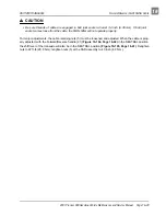
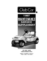
Figure 16-80 Casing Torque Sequence
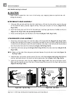
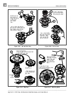
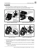
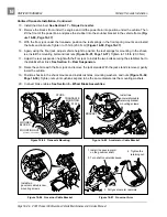
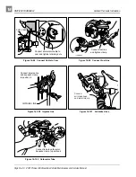
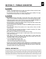
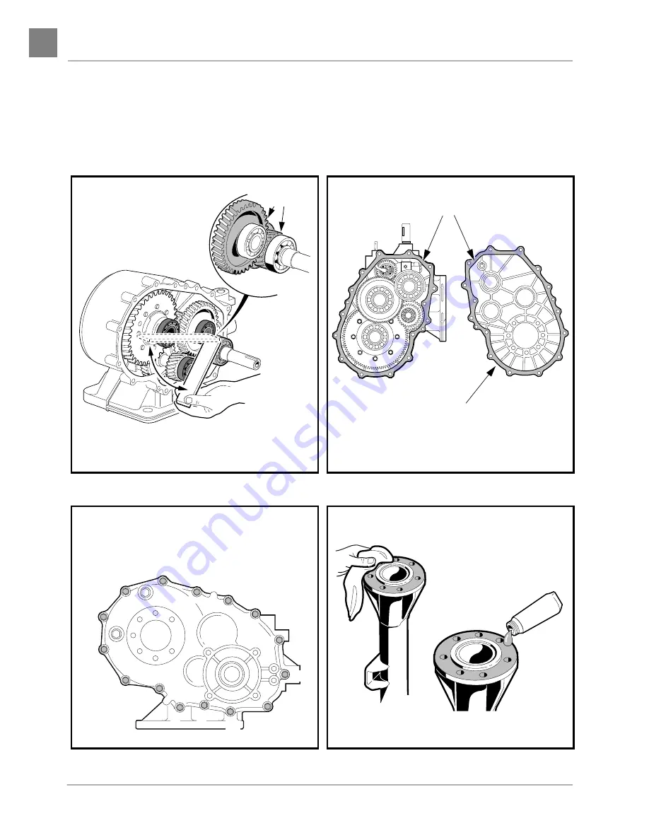
Figure 16-81 Axle Tube Surface
The outside edges of the idler, intermediate,
and differential bearings are on the same plane.
The synchronizer bearing protrudes slightly.
The edges of the input
drive gear and large
intermediate gear
should be flush.
EDGES
FLUSH
Clean mating surfaces of any oil,
dirt, grease or residue of any kind.
After cleaning mating surfaces, apply
a continuous bead of Three Bond No.
1215 completely around the mating
surface of the right side casing and
around all bolt holes.
In the sequence shown, torque to
17 ft-lb (23.1 N·m) the fifteen bolts that
secure the casing together.
1
3
5
6
7
8
9
11
13
14
15
4
2
10
12
Clean the mating surface of
the right axle tube, then apply
a continuous bead of
Three Bond No. 1215 to
mating surface.

