FE350 ENGINE
Crankshaft and Counterbalance
2001 Pioneer 900 Gasoline Vehicle Maintenance and Service Manual Page 13-43
13
Crankshaft Installation
∆ WARNING
• Before assembly, make sure all parts are clean.
NOTE: When reassembling the crankshaft and the counterbalance weight, apply a light film of engine oil to
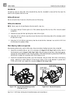
the crankshaft journals and guide shaft (Figure 13-93, Page 13-42).
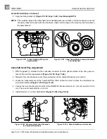
1. Installation is the reverse of removal. See Crankshaft and Counterbalance Removal on page 13-35.
2. Tighten the four nuts (2) for counterbalance guide shaft to 50 in-lb (5.9 N·m) (Figure 13-73, Page 13-35).
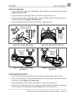
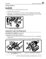
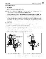
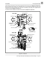
3. If the link rod was removed from the PTO side of the crankshaft, support the crankweb as shown, slide
the link rod onto the crankshaft, and install the key. Press the spur gear and helical gear onto the crank-
shaft (Figure 13-94, Page 13-43 and Figure 13-95, Page 13-43). See following CAUTION and
NOTE.
∆ CAUTION
• Use a press when removing or installing the spur gear and helical gear on the crankshaft.
• If the spur gear was warped while being removed, install a new one.
NOTE: Make sure the chamfered inside diameters of the spur gear and helical gear are oriented downward
on the crankshaft as shown (Figure 13-94, Page 13-43).
Make sure the link rods rotate smoothly after the gears are pressed on.
4. Slide the link rod, then the spacer, onto the flywheel end of the crankshaft.
Figure 13-94 Crankshaft Installation
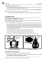
Figure 13-95 Press on Spur Gear and Helical Gear
PRESS
SLEEVE
PRESS
TABLE
SPUR GEAR (CHAMFERED INSIDE
DIAMETER FACING DOWN)
LINK ROD
KEY
HELICAL
GEAR
(NOTE
TIMING
MARK)
PRESS RAM

