STEERING AND FRONT SUSPENSION
Front Suspension
2001 Pioneer 900 Gasoline Vehicle Maintenance and Service Manual Page 7-15
7
∆ CAUTION
• To ensure proper lubrication of the front suspension and steering linkages, raise front of vehicle to
lubricate. See WARNING on page 7-1.
WHEEL ALIGNMENT
Wheel alignment is limited to equalizing the camber angle of each front wheel and adjusting toe-in of the
front wheels. There is also a drag link adjustment to equalize the turning radius in both directions. See Steer-
ing Adjustment on page 7-7.
NOTE: Prior to making any front suspension adjustments, inspect components for wear or damage and
repair or replace as necessary.
Camber Adjustment
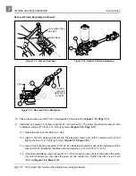
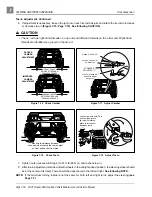
1. Check each front wheel with a framing square. At the floor (or ground), there should be an equal
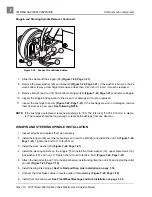
amount of space between each tire and the framing square (Figure 7-16, Page 7-16).
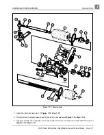
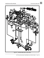
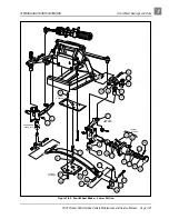
2. Loosen (do not remove) the four bolts (30) that secure the leaf spring (6) to the bottom spring plate (29)
(Figure 7-22, Page 7-21). See also Figure 7-17, Page 7-16.
3. Loosen (do not remove) the hex nut (8) on the adjustment eccentric (7) (Figure 7-17, Page 7-16) in the
center of the spring. See also Figure 7-22, Page 7-21.
4. Use a 7 mm deep well socket to rotate the eccentric (Figure 7-17, Page 7-16).
5. After adjusting camber, tighten the four spring retaining bolts (30) (Figure 7-22, Page 7-21) to 23 ft-lb
(31 N·m). Then roll the vehicle forward one full tire revolution and recheck the camber. See also Figure
7-16, Page 7-16.
6. Tighten the hex nut (8) on the adjustment eccentric (7) to 10 ft-lb (13.5 N·m) (Figure 7-22, Page 7-21)
See also Figure 7-17, Page 7-16.
Toe-in Adjustment
1. On a level surface, roll the vehicle forward, then stop. Make sure the front wheels are pointed straight
ahead. Do not turn the steering wheel again during this procedure.
2. On each front tire, mark (as closely as possible) the center of the tread face that is oriented toward the
rear of the vehicle. The marks should be even with the bottom surfaces of the vehicle frame I-beams.
3. Measure the distance between the marks on the rear-facing surfaces of the tires, and then roll the vehi-
cle forward one and one-half wheel revolutions until the marks appear on the forward facing surfaces of
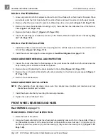
the tires at about the same height from the floor (Figure 7-18, Page 7-16).
4. Measure the distance between the marks on the forward-facing surfaces of the tires.
NOTE: The front measurement must be less than the rear measurement.
5. Subtract the measurement on the front of the tires from the measurement on the rear of the tires. The
difference is the toe-in. Proper toe-in is 1/8 to 3/8 of an inch (3.2 to 9.5 mm).

