ELECTRICAL COMPONENTS (GASOLINE
VEHICLE)
Reverse Warning Buzzer
20
TESTING THE REVERSE WARNING BUZZER
See Test Procedure 18 – Reverse Buzzer on page 19-30.
REVERSE WARNING BUZZER REMOVAL
1.
Disconnect battery and spark plug wire(s).
See Disconnecting the Battery – Gasoline Vehicles on page 1-3.
2.
Remove the instrument panel.
See Key Switch Removal on page 20-14.
3.
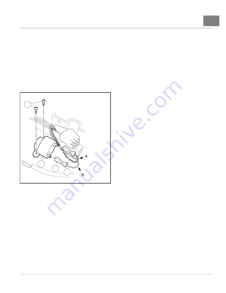
Disconnect the wires from the reverse warning buzzer (2)
.
4.
Remove the two mounting screws (3) securing the buzzer to the instrument panel.
3
2
1
4
A, Red/White wire B. Black wire
711
Figure 20-21
Reverse Buzzer
REVERSE WARNING BUZZER INSTALLATION
1.
Install the screws (3) through the buzzer bracket tabs and tighten to 3.5 in·lb (0.40 N·m)
2.
Connect the black wire (1) from the wire harness to the negative (–) terminal on the buzzer.
3.
Connect the red/white wire (4) from the wire harness to the positive (+) terminal on the buzzer.
4.
Install the instrument panel.
4.1. Connect the electrical connector (3)
4.2. Position the instrument panel (2) on the dash assembly. Make sure tabs on upper edge properly engage
with the corresponding slots on the dash assembly. Ensure that there are no wires exposed or pinched
during positioning.
4.3. Secure instrument panel to the dash assembly with three screws (1). Tighten screws to 1.8 ft·lb (2.5 N·m).
5.
Connect battery and spark plug wire(s).
See Connecting the Battery – Gasoline Vehicles on page 1-4.
6.
Shift the Forward/Reverse handle to the REVERSE position. The buzzer should sound.
2014 Precedent
®
Golf Car Maintenance and Service Manual
Page 20-19
Summary of Contents for Precedent 2014
Page 2: ......
Page 4: ......
Page 24: ......
Page 28: ......
Page 38: ......
Page 66: ......
Page 104: ......
Page 116: ......
Page 152: ......
Page 234: ......
Page 252: ......
Page 264: ......
Page 298: ......
Page 332: ......
Page 394: ......
Page 412: ......
Page 438: ......
Page 444: ......
Page 508: ......
Page 534: ......
Page 543: ......
Page 544: ......
Page 545: ......
Page 547: ......
Page 548: ......


