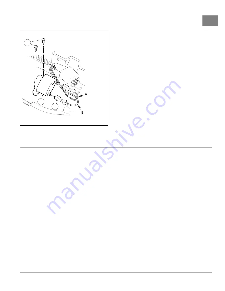
ELECTRICAL COMPONENTS: ELECTRIC VEHICLE
WITH POWERDRIVE CHARGER
Electronics Module
14
3
2
1
4
(Viewed from underside of instrument panel)
A. Pink B. Orange/White
711
Figure 14-7
Reverse Buzzer
ELECTRONICS MODULE
See General Warnings on page 1-2.
While it is not necessary to remove the electronics module from the vehicle, access to individual components may be
easier with the module removed.
ELECTRONICS MODULE REMOVAL
1.
Disconnect the batteries and discharge the controller.
See Disconnecting the Batteries – Electric Vehicles
2.
Remove the batteries from the vehicle to provide enough room to access the controller (8)
See Battery Replacement on page 15-9.
3.
Remove the bolt (11) that secures the electronics module to the battery bucket.
4.
Pull electronics module forward and disconnect the heavy gauge wires from the controller by removing the
three screws (9).
5.
Disconnect the 16-pin connector, 4-pin connector, and spade connectors from the controller.
6.
Remove the three self-tapping screws (10) that hold the controller to the component mounting plate (14) and
remove the controller from the vehicle.
7.
Remove two nuts (3) on top of the solenoid (5) posts and remove the wires from the posts.
8.
Disconnect the spade connectors on the front of the solenoid.
9.
Disconnect the 6-pin connector and all other leads from the onboard computer (OBC) (15) and the two wires from
Tow/Run switch.
10. Lift the electronics module from the vehicle.
See following WARNING.
2014 Precedent
®
Golf Car Maintenance and Service Manual
Page 14-9
Summary of Contents for Precedent 2014
Page 2: ......
Page 4: ......
Page 24: ......
Page 28: ......
Page 38: ......
Page 66: ......
Page 104: ......
Page 116: ......
Page 152: ......
Page 234: ......
Page 252: ......
Page 264: ......
Page 298: ......
Page 332: ......
Page 394: ......
Page 412: ......
Page 438: ......
Page 444: ......
Page 508: ......
Page 534: ......
Page 543: ......
Page 544: ......
Page 545: ......
Page 547: ......
Page 548: ......


