20
Ignition Coil
ELECTRICAL COMPONENTS (GASO-
LINE VEHICLE)
CAP
8
6
7
4
3
1
2
5
0.012 Inch
(0.304 mm)
6
511
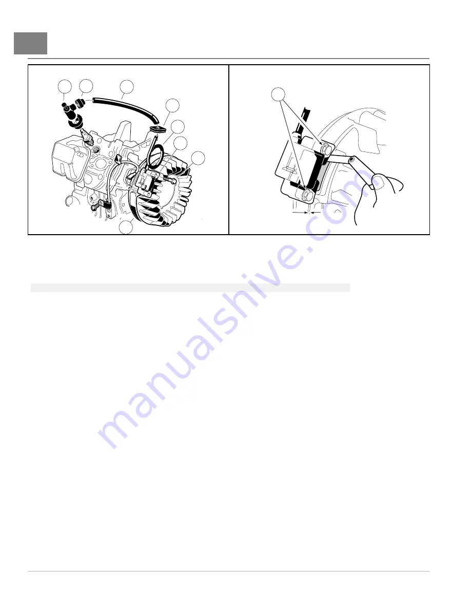
Figure 20-28
Clean Grommet
512
Figure 20-29
Mount Ignition Coil Using Feeler Gauge
3.
Remove the gasket (1) and protector tube (3) from the old coil.
See following NOTE.
NOTE:
Moisten the spark plug wire with water to make gasket removal and installation easier.
4.
Remove the grommet (4) from the old spark plug wire. Clean the grommet and place it on the new spark plug
wire (5).
5.
Install the protector tube onto the new wire.
6.
Slide the gasket onto the end of the new spark plug wire.
7.
Install the cap on the new coil spark plug wire by rotating it clockwise three or four revolutions while applying
light pressure on the cap.
8.
Install the gasket (1) on the cap (2).
9.
Position the ignition coil (7) onto the cast mounting bosses on the engine crankcase and tighten the two mounting
bolts (6) to finger-tight at this time.
10. Rotate the flywheel (8) until the magnet is positioned directly under the ignition coil. Use a 0.012 inch (0.304
mm) bronze feeler gauge to set the air gap between the ignition coil and the flywheel magnet. Tighten the two
mounting bolts (6) to 30 in·lb (3.4 N·m)
.
11. Connect the 18-gauge black wire to the spade terminal on the coil.
12. Position the fan housing close to the engine crankcase and slide the plug wire grommet into the notch on the
housing.
13. When installing fan housing, make sure the top front corner of the housing is above the upper cylinder shroud.
The front edge of the fan housing should be behind the lower cylinder shroud. Align the slots in the housing
with the flanged bolts loosened earlier.
14. Install the four remaining flange bolts that secure the fan housing to the engine crankcase. Tighten all seven
mounting bolts to 90 in·lb (10.2 N·m)
15. Install the stiffener with four hex-head bolts and lock nuts. Tighten the hardware to 23 ft·lb (30.5 N·m).
16. Install the fan shroud with four pan-head bolts (5). Tighten to 50 in·lb (5.7 N·m)
.
17. Secure the wire harness to the stiffener with a wire tie. Place the wire tie through the lower hole at the back of
the stiffener
Page 20-26
2014 Precedent
®
Golf Car Maintenance and Service Manual
Summary of Contents for Precedent 2014
Page 2: ......
Page 4: ......
Page 24: ......
Page 28: ......
Page 38: ......
Page 66: ......
Page 104: ......
Page 116: ......
Page 152: ......
Page 234: ......
Page 252: ......
Page 264: ......
Page 298: ......
Page 332: ......
Page 394: ......
Page 412: ......
Page 438: ......
Page 444: ......
Page 508: ......
Page 534: ......
Page 543: ......
Page 544: ......
Page 545: ......
Page 547: ......
Page 548: ......


