24
Unitized Transaxle Installation
UNITIZED TRANSAXLE (GASOLINE VEHICLE)
17. Connect brake cables.
See Brake Cable Installation on page 6-14.
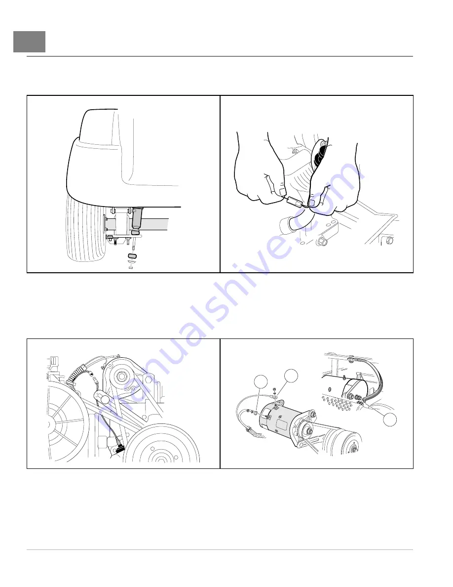
18. Route the engine kill switch wire (18-gauge white/black) through the same retainers that hold the accelerator
cable. Connect the wire to the bullet connector at the lower right front of the engine
.
767
Figure 24-47
Shock Absorber
569
Figure 24-48
Ignition Kill Wire
19. Connect the oil level sensor wire (18-gauge yellow) to the jumper wire
20. Connect the 6-gauge white wire to the F2 post, the 6-gauge black ground wire to the A2 post and tighten both
wires to 48 in·lb (5.4 N·m). Connect the 16-gauge yellow wire to the DF post on the starter/generator and
tighten to 30 in·lb (3.4 N·m)
DF
F2
DF
1
2
3
1. Yellow Wire 2. White Wire 3. Ground Wire at A2 Terminal
568
Figure 24-49
Oil Level Sensor Jumper wire
1350
Figure 24-50
Starter/Generator – Model 114-01-4005
shown
21. Route shifter cable through the shifter cable bracket. Ensure the cable boot is properly positioned through the
bracket. The clips on the boot should hold the cable in place. Connect shifter cable rod end to the shifter
arm
22. Attach the ground wire to the mounting screw on the oil filler tube mounting bracket and tighten to 50 in·lb
(5.7 N·m)
.
Page 24-20
2014 Precedent
®
Golf Car Maintenance and Service Manual
Summary of Contents for Precedent 2014
Page 2: ......
Page 4: ......
Page 24: ......
Page 28: ......
Page 38: ......
Page 66: ......
Page 104: ......
Page 116: ......
Page 152: ......
Page 234: ......
Page 252: ......
Page 264: ......
Page 298: ......
Page 332: ......
Page 394: ......
Page 412: ......
Page 438: ......
Page 444: ......
Page 508: ......
Page 534: ......
Page 543: ......
Page 544: ......
Page 545: ......
Page 547: ......
Page 548: ......


