ELECTRICAL COMPONENTS
Motor Controller Output Regulator (MCOR)
13
MOTOR CONTROLLER OUTPUT REGULATOR (MCOR)
See General Warnings on page 1-2.
TESTING THE MCOR
See Test Procedure 12 – MCOR Voltage on page 12-24 and Test Procedure 7 – Key Switch and MCOR Limit
Switch Circuit on page 12-20.
MCOR REMOVAL
1.
Disconnect the batteries and discharge the controller.
See Disconnecting the Batteries – Electric Vehicles,
2.
Place chocks at rear wheels and lift the front of the vehicle with a chain hoist or floor jack. Place jack stands
under the round tube crossmember of the frame to support vehicle.
3.
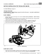
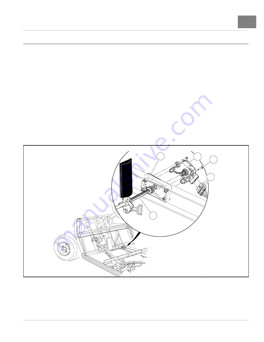
Disconnect the two-pin and three-pin connectors (1) from the MCOR (2)
.
4.
Remove the two torx screws (3) securing the MCOR (2) to the plastic housing (4) on the chassis.
5.
Detach the two tabs from the plastic housing (4) and remove the MCOR (2) from vehicle.
G
O
1
2
3
4
5
2646
Figure 13-3
MCOR Mounting
MCOR INSTALLATION
1.
Align the two tabs of the MCOR (2) with the slots in the plastic housing (4) on the chassis
. Insert the MCOR into the plastic housing (4) until the tabs engage.
See following NOTE.
2019 Transporter Maintenance and Service Manual
Page 13-5
Summary of Contents for TransPorter 4
Page 2: ......
Page 271: ...ELECTRIC MAIN HARNESS Wiring Diagrams Electric Main Harness 18 ...
Page 272: ... Page intentionally left blank ...
Page 273: ...ELECTRIC INSTRUMENT PANEL HARNESS Wiring Diagrams Electric Instrument Panel Harness 18 ...
Page 274: ... Page intentionally left blank ...
Page 275: ...ELECTRIC ACCESSORIES HARNESS Wiring Diagrams Electric Accessories Harness 18 ...
Page 276: ... Page intentionally left blank ...
Page 282: ...NOTES ...
Page 283: ...NOTES ...
Page 284: ...NOTES ...
Page 285: ......
Page 286: ......

