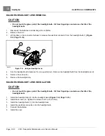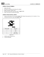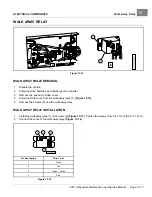
ELECTRICAL COMPONENTS
Solenoid
13
SOLENOID
See General Warnings on page 1-2.
The solenoid is located on the passenger side of the electrical component mounting plate.
TESTING THE SOLENOID
See Test Procedure 9 – Solenoid Activating Coil on page 12-22 and Test Procedure 10 – Solenoid Contacts on
page 12-23.
SOLENOID REMOVAL
1.
Disconnect the batteries and discharge the controller.
See Disconnecting the Batteries – Electric Vehicles,
2.
Remove the speed controller cover.
See Removing the Speed Controller Cover on page 13-6.
3.
Disconnect all wires from the solenoid
4.
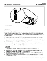
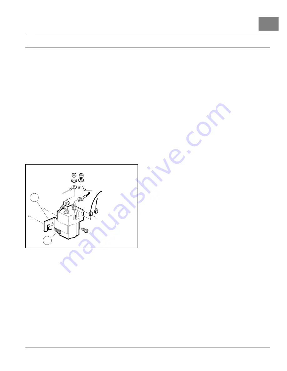
Loosen, but do not remove, the two screws (1) that hold the solenoid (2) to the component mounting plate.
5.
Lift the solenoid (2) up and off of the component mounting plate.
2
1
Figure 13-4
Solenoid
SOLENOID INSTALLATION
1.
Mount solenoid (2) onto component mounting plate with screws (1)
2.
Tighten screws (1) to 60 in·lb (6.8 N·m).
3.
Using the wiring diagram, install the wires, washers, and nuts onto the large mounting posts. Tighten nuts to
77 in·lb (8.7 N·m).
4.
Install the blue/white and light blue wires onto the small terminals of the solenoid
.
5.
Install speed controller cover.
See See Installing the Speed Controller Cover on page 13-6.
6.
Connect the batteries.
See Connecting the Batteries – Electric Vehicles, Section 1, Page 1-4.
2019 Transporter Maintenance and Service Manual
Page 13-7
Summary of Contents for TransPorter 4
Page 2: ......
Page 271: ...ELECTRIC MAIN HARNESS Wiring Diagrams Electric Main Harness 18 ...
Page 272: ... Page intentionally left blank ...
Page 273: ...ELECTRIC INSTRUMENT PANEL HARNESS Wiring Diagrams Electric Instrument Panel Harness 18 ...
Page 274: ... Page intentionally left blank ...
Page 275: ...ELECTRIC ACCESSORIES HARNESS Wiring Diagrams Electric Accessories Harness 18 ...
Page 276: ... Page intentionally left blank ...
Page 282: ...NOTES ...
Page 283: ...NOTES ...
Page 284: ...NOTES ...
Page 285: ......
Page 286: ......

