ELECTRICAL COMPONENTS
Emergency Stop Switch
13
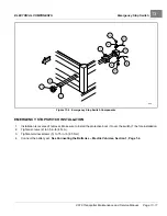
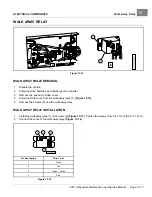
Figure 13-6
Emergency Stop Switch Components
EMERGENCY STOP SWITCH INSTALLATION
1.
Installation is reverse of removal. Make sure to install the protective boot (3) over the switch (7) before installation.
2.
Tighten screws (2) to 35 in·lb (4 N·m).
3.
Tighten terminal screws (5) to 75 in·lb (8.5 N·m).
4.
Connect the battery set.
See Connecting the Batteries – Electric Vehicles, Section 1, Page 1-4.
2019 Transporter Maintenance and Service Manual
Page 13-11
Summary of Contents for TransPorter 4
Page 2: ......
Page 271: ...ELECTRIC MAIN HARNESS Wiring Diagrams Electric Main Harness 18 ...
Page 272: ... Page intentionally left blank ...
Page 273: ...ELECTRIC INSTRUMENT PANEL HARNESS Wiring Diagrams Electric Instrument Panel Harness 18 ...
Page 274: ... Page intentionally left blank ...
Page 275: ...ELECTRIC ACCESSORIES HARNESS Wiring Diagrams Electric Accessories Harness 18 ...
Page 276: ... Page intentionally left blank ...
Page 282: ...NOTES ...
Page 283: ...NOTES ...
Page 284: ...NOTES ...
Page 285: ......
Page 286: ......

