15
Troubleshooting
BATTERY CHARGER
TROUBLESHOOTING
See General Warnings on page 1-2.
DANGER
• Do not touch any wire or component in the battery charger while AC power is present. Failure to
heed this warning will result in an electric shock.
WARNING
• Knowledge of battery charger wiring and component terminology is required before attempting any
repair (Figure 15-2, Page 15-3).
• Prior to servicing the charger, disconnect the AC power supply cord from the wall outlet and remove
the battery charger from the vehicle. See Onboard Charger Removal And Installation on page 15-12.
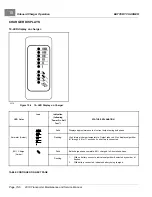
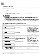
If a fault occurs, count the number of red flashes (on the charger or dash) between pauses and refer to the table below:
HIGH FREQUENCY BATTERY CHARGER TROUBLESHOOTING GUIDE
RED FLASHES
CAUSE
SOLUTION
Battery High Voltage
Ensure battery set is rated 48 volts and
composed of 24 cells.
Using Multimeter on page 15-11.
If not, replace with correct battery set. Reset
charger (interrupt AC power for 15 seconds).
Battery Low Voltage
Ensure battery set is rated 48 volts and
composed of 24 cells. Also, check the voltage
of each individual battery.
Voltage Using Multimeter on page 15-11.
not, replace with correct battery set. Reset
charger (interrupt AC power for 15 seconds).
Charge Timeout caused by battery pack not
reaching required voltage.
Charger output was reduced due to high
temperatures
Check for loose or corroded connections.
Check for old or defective batteries.
Operate charger at a lower ambient
temperature.
Check Battery: battery could not be trickle
charged up to minimum voltage
Check for shorted or damaged cells.
Battery Voltage Using Multimeter on page
Over-Temperature: Charger shut down due to
high internal temperature
Check for dirty, obstructed, or damaged
cooling fins. Clean if necessary and ensure
sufficient cooling air flow. Reset charger
(interrupt AC power for 15 seconds).
Charger Internal Fault
Reset charger (interrupt AC power for 15
seconds). Return to qualified service depot if
fault persists.
Page 15-10
2019 Transporter Maintenance and Service Manual
Summary of Contents for TransPorter 4
Page 2: ......
Page 271: ...ELECTRIC MAIN HARNESS Wiring Diagrams Electric Main Harness 18 ...
Page 272: ... Page intentionally left blank ...
Page 273: ...ELECTRIC INSTRUMENT PANEL HARNESS Wiring Diagrams Electric Instrument Panel Harness 18 ...
Page 274: ... Page intentionally left blank ...
Page 275: ...ELECTRIC ACCESSORIES HARNESS Wiring Diagrams Electric Accessories Harness 18 ...
Page 276: ... Page intentionally left blank ...
Page 282: ...NOTES ...
Page 283: ...NOTES ...
Page 284: ...NOTES ...
Page 285: ......
Page 286: ......


