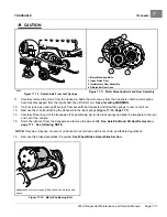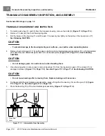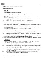
TRANSAXLE
Transaxle Disassembly, Inspection, and Assembly
17
8.
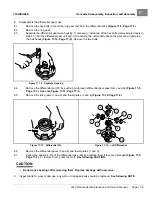
Disassemble the differential gear case:
8.1.
Remove the hex bolts (33) and the ring gear (32) from the differential case
8.2.
Remove the ring gear.
8.3.
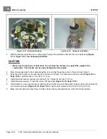
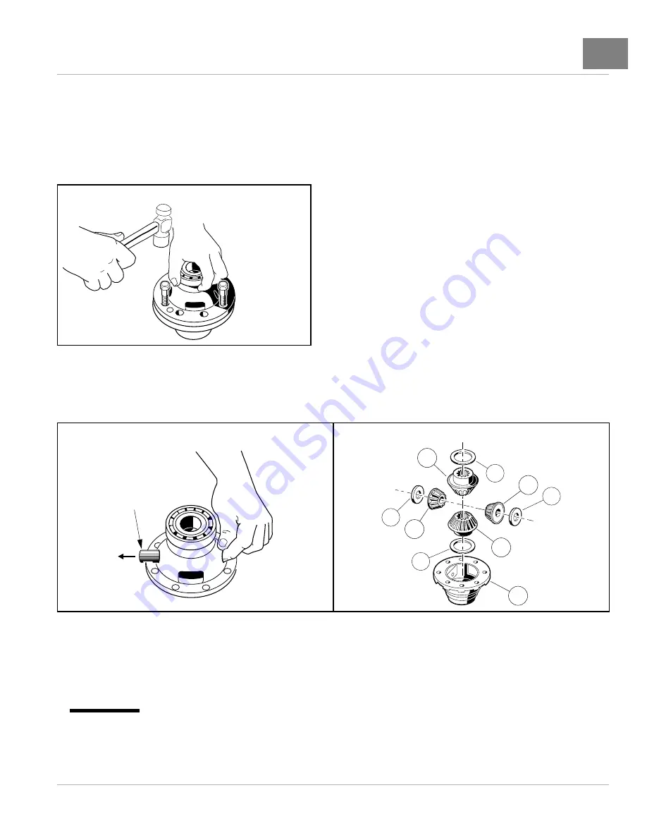
Separate the differential gear case housing. If necessary, install two of the hex bolts (removed previously in
step 8.1) into the differential gear unit and, while holding the unit slightly above the work area, lightly tap
the bolt heads
. Remove the two bolts.
Figure 17-14
Separate Housing
8.4.
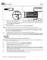
Remove the differential pin (31) by pushing pin through differential gear case from one side
.
See also Figure 17-15, Page 17-9.
8.5.
Remove the idler gears (1 and 2) and thrust plates (3 and 4)
1
5
6
26
2
8
7
3
4
Figure 17-15
Differential Pin
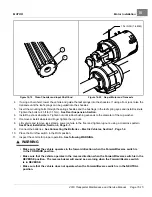
Figure 17-16
Left Differential
8.6.
Remove the differential gears (5 and 6) and thrust plates (7 and 8).
8.7.
Inspect the bearings (13) of the differential case (26) and replace them if they are damaged
. To remove them, press them off.
See following CAUTION.
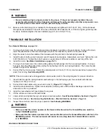
CAUTION
• Do not reuse bearings after removing them. Replace bearings with new ones.
9.
Inspect parts for wear or damage. Any worn or damaged parts should be replaced.
See following NOTE.
2019 Transporter Maintenance and Service Manual
Page 17-9
Summary of Contents for TransPorter 4
Page 2: ......
Page 271: ...ELECTRIC MAIN HARNESS Wiring Diagrams Electric Main Harness 18 ...
Page 272: ... Page intentionally left blank ...
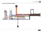
Page 273: ...ELECTRIC INSTRUMENT PANEL HARNESS Wiring Diagrams Electric Instrument Panel Harness 18 ...
Page 274: ... Page intentionally left blank ...
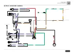
Page 275: ...ELECTRIC ACCESSORIES HARNESS Wiring Diagrams Electric Accessories Harness 18 ...
Page 276: ... Page intentionally left blank ...
Page 282: ...NOTES ...
Page 283: ...NOTES ...
Page 284: ...NOTES ...
Page 285: ......
Page 286: ......


