ELECTRICAL SYSTEM TROUBLESHOOTING
Test Procedures
12
5.
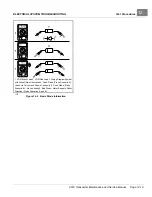
A fully charged set of batteries in good condition should read between 47 and 49 volts while under load.
6.
A reading of 32 to 42 volts indicates discharged or failed batteries. Each battery should be checked with a
multimeter while under load.
See following NOTE.
NOTE:
If a 48-volt set of batteries is down in the 32 to 38 volt range, the discharge machine will activate but it will
think it is testing a 36-volt battery set.
7.
A reading of 31.5 volts or less will not activate discharge machine. If the voltage of the batteries is below 32 volts,
the batteries are deeply discharged or have failed.
8.
Recording the battery pack voltage reading while under load provides a more accurate diagnosis of the condition
of the batteries. When the discharge machine is ON, it places the battery pack under load and many times
can help determine if one or more batteries in the set have failed. Testing battery voltage while the batteries
are not under load will not always indicate the true condition of the batteries. For more information about the
batteries, refer to Section 14 — Batteries
TEST PROCEDURE 3 – Run/Tow Switch
See General Warnings on page 1-2.
NOTE:
This is a voltage test.
If no voltage is coming to the Run/Tow Switch, inspect the 12-gauge red wire connection at the solenoid
and sonic weld 12.
Run/Tow Switch Test with the CDT Handset
1.
With the Run/Tow switch in the RUN position, connect the CDT to the vehicle.
2.
Immediately after the CDT is connected to the vehicle, the screen should display a copyright notice and the
CDT model number.
3.
If the CDT display screen is blank, drive the vehicle a short distance to activate the onboard computer.
4.
If the vehicle will not operate, proceed to
Run/Tow Switch Test without the CDT Handset
.
5.
If the CDT display screen begins to work after the vehicle has been driven, turn the key switch to the OFF position
and proceed to step 6; otherwise, perform
Run/Tow Switch Test without the CDT Handset
.
6.
With the CDT still connected to the vehicle, place the Run/Tow Switch in the TOW position and wait 90 seconds.
7.
If the CDT display screen goes blank, the Run/Tow switch and connecting wires are operating correctly.
8.
If the CDT display screen is still active after 90 seconds, the switch has failed closed. Replace the Run/Tow
switch.
See Run/Tow Switch Removal on page 13-3.
Run/Tow Switch Test without the CDT Handset
1.
Set a multimeter to 200 volts DC. With the batteries connected, and the Run/Tow switch in either the TOW or
RUN position, connect the black (–) probe to the negative post of battery no. 8 and connect red (+) probe (with
insulation-piercing probe) on the pink wire close to the two-pin connector on the Run/Tow switch.
2.
If the reading is 48 to 50 volts, proceed to Step 3. If the voltage reading is 0 volts, check wire continuity from the
large post of the solenoid (red, 12-gauge wire (w80) attached), through sonic weld 12 (where it changes to a pink,
16-gauge wire (w50)), to the pink wire side of the Run/Tow switch two-pin connector.
3.
Set a multimeter to 200 volts DC and with the batteries connected, connect the black (–) probe to the negative
post of battery no. 8 and connect red (+) probe (with insulation-piercing probe) on the light green wire (1)
close to the two-pin connector on the Run/Tow switch.
4.
With the Run/Tow switch in the RUN position, the reading should be approximately 48 to 50 volts. With the switch
in the TOW position, the reading should be approximately 0 volts.
5.
If the two-pin connector and pink wire continuity readings are correct, replace the Run/Tow switch.
2019 Transporter Maintenance and Service Manual
Page 12-15
Summary of Contents for TransPorter 4
Page 2: ......
Page 271: ...ELECTRIC MAIN HARNESS Wiring Diagrams Electric Main Harness 18 ...
Page 272: ... Page intentionally left blank ...
Page 273: ...ELECTRIC INSTRUMENT PANEL HARNESS Wiring Diagrams Electric Instrument Panel Harness 18 ...
Page 274: ... Page intentionally left blank ...
Page 275: ...ELECTRIC ACCESSORIES HARNESS Wiring Diagrams Electric Accessories Harness 18 ...
Page 276: ... Page intentionally left blank ...
Page 282: ...NOTES ...
Page 283: ...NOTES ...
Page 284: ...NOTES ...
Page 285: ......
Page 286: ......


