ELECTRICAL SYSTEM TROUBLESHOOTING
Test Procedures
12
2.
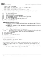
Disconnect the batteries and discharge the controller.
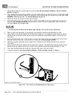
See Disconnecting the Batteries – Electric Vehicles
3.
Access the solenoid by removing the electronics module cover.
See Removing the Speed Controller Cover on
4.
Remove the two small wire terminals from the solenoid.
5.
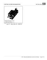
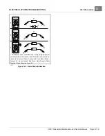
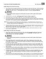
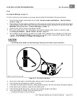
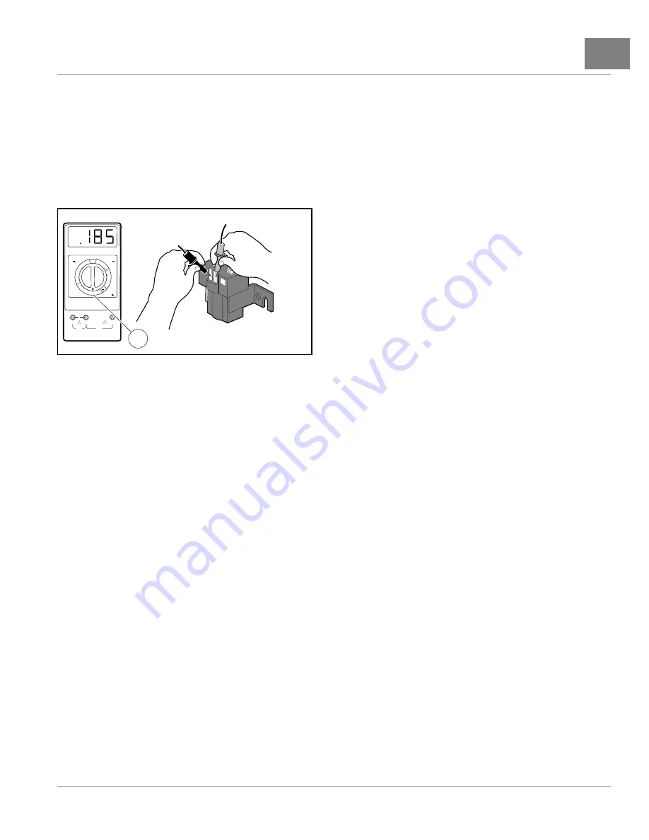
Place red (+) probe of the multimeter on the positive (+) solenoid terminal. Place the black (–) probe on the
other small solenoid terminal.
– A reading of 180 to 190 ohms should be obtained
. If not, replace the solenoid.
+
2m
20
m
200
m
2k
200
200
200
200
20
2
200
m
500
20k
200k
2000
k
1000
OFF
WAVETEK
5XL
V
V
V
A
!
!
COM
200nA
MAX
1000 ---
750V
FUSED
1
2500-20000-10283
Figure 12-7
Activating Coil Test – Service Replacement
Solenoid
TEST PROCEDURE 10 – Solenoid Contacts
See General Warnings on page 1-2.
NOTE:
Unlike other controllers used by Club Car, the pre-charge resistor is internal to the IQ Plus controller.
1.
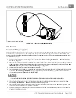
Place chocks at the front wheels and lift the rear of the vehicle with a chain hoist or floor jack. Position jack stands
under the frame crossmember between the spring mount and side stringer, just forward of each rear wheel.
See
WARNING “Lift only one end...” in General Warnings on page 1-2.
2.
Turn the key switch to the ON position and place the Forward/Reverse switch in the FORWARD position.
3.
Set a multimeter to 200 volts. Place the black (–) probe on the battery no. 8 negative post and place the red (+)
probe on the large post with the 6-gauge yellow wire.
4.
With the pedal up, the reading should be 9.5 to 10.5 volts. If the voltage is higher, let the car sit for 5 to 10 minutes
to allow the capacitors to discharge to 9.5 to 10.5 volts.
5.
Press the accelerator pedal. The voltage should read 48 to 50 volts with the pedal pressed. If the voltage does
not increase or goes to 0 volts with the pedal pressed, replace the solenoid.
TEST PROCEDURE 11 – Charger Interlock
See General Warnings on page 1-2.
Controller Interlock Function Test with the CDT Handset
1.
If necessary, see
See Testing Basics, Section 12, Page 12-11.
2.
Connect the CDT to the vehicle.
3.
Access the Monitor menu and select CHARGER INHIBIT by using the SCROLL DISPLAY buttons. The CDT
should indicate OFF.
2019 Transporter Maintenance and Service Manual
Page 12-23
Summary of Contents for TransPorter 4
Page 2: ......
Page 271: ...ELECTRIC MAIN HARNESS Wiring Diagrams Electric Main Harness 18 ...
Page 272: ... Page intentionally left blank ...
Page 273: ...ELECTRIC INSTRUMENT PANEL HARNESS Wiring Diagrams Electric Instrument Panel Harness 18 ...
Page 274: ... Page intentionally left blank ...
Page 275: ...ELECTRIC ACCESSORIES HARNESS Wiring Diagrams Electric Accessories Harness 18 ...
Page 276: ... Page intentionally left blank ...
Page 282: ...NOTES ...
Page 283: ...NOTES ...
Page 284: ...NOTES ...
Page 285: ......
Page 286: ......


