13
Reverse Buzzer
ELECTRICAL COMPONENTS
NOTE:
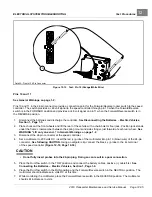
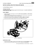
Rotate the drive bar (5) back and forth if necessary to align the D-shaped end with the MCOR.
2.
Secure the MCOR (2) to the plastic housing (4) with two torx screws (3). Tighten screws to 12 in·lb (1.4 N·m).
3.
Connect the two-pin and three-pin connectors (1) from the wire harness to the MCOR (2).
4.
Connect the batteries.
See Connecting the Batteries – Electric Vehicles, Section 1, Page 1-4.
REVERSE BUZZER
See General Warnings on page 1-2.
TESTING THE REVERSE BUZZER
See Test Procedure 16 – Reverse Buzzer on page 12-39.
REVERSE BUZZER REMOVAL
1.
Disconnect the batteries and discharge the controller.
See Disconnecting the Batteries – Electric Vehicles,
2.
Remove the instrument panel.
See Instrument Panel Removal, Section 4, Page 4-9.
3.
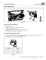
Disconnect the 18-gauge pink and orange/white wires from reverse buzzer.
4.
Remove the two screws from the reverse buzzer. Remove the reverse buzzer from the center dash panel.
REVERSE BUZZER INSTALLATION
1.
Install the reverse buzzer in the reverse order of removal. Tighten screws to 4 in·lb (0.45 N·m).
2.
Connect the batteries.
See Connecting the Batteries – Electric Vehicles, Section 1, Page 1-4.
SPEED CONTROLLER COVER
REMOVING THE SPEED CONTROLLER COVER
1.
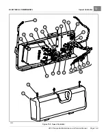
Use a flathead screwdriver to pry up the center pieces of the 3 push rivets (5) and remove the rivets
.
2.
Pull the speed controller cover (9) down and away from the component mounting plate.
3.
Lift the curved edges of the speed controller cover out of the slots in the component mounting plate.
INSTALLING THE SPEED CONTROLLER COVER
1.
Place the curved edges on the bottom of the speed controller cover into the slots on the component mounting
plate.
2.
Press the speed controller cover onto the component mounting plate over the speed controller and other
electrical components.
3.
Install the three push rivets (5)
Page 13-6
2019 Transporter Maintenance and Service Manual
Summary of Contents for TransPorter 4
Page 2: ......
Page 271: ...ELECTRIC MAIN HARNESS Wiring Diagrams Electric Main Harness 18 ...
Page 272: ... Page intentionally left blank ...
Page 273: ...ELECTRIC INSTRUMENT PANEL HARNESS Wiring Diagrams Electric Instrument Panel Harness 18 ...
Page 274: ... Page intentionally left blank ...
Page 275: ...ELECTRIC ACCESSORIES HARNESS Wiring Diagrams Electric Accessories Harness 18 ...
Page 276: ... Page intentionally left blank ...
Page 282: ...NOTES ...
Page 283: ...NOTES ...
Page 284: ...NOTES ...
Page 285: ......
Page 286: ......

