17
Transaxle Disassembly, Inspection, and Assembly
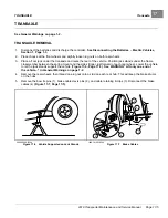
TRANSAXLE
TRANSAXLE DISASSEMBLY, INSPECTION, AND ASSEMBLY
See General Warnings on page 1-2.
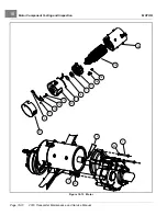
TRANSAXLE DISASSEMBLY AND INSPECTION
1.
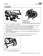
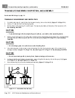
To detach axle tubes (14 and 35) from the transaxle housing, remove the bolts (8)
.
2.
Remove 11 bolts (24) that hold housing together.
3.
Pull the halves of the housing (11 and 20) apart. If necessary, tap lightly on the spline of the input pinion (17).
See following CAUTION.
CAUTION
• To prevent damage to the housing mating seal surfaces, use caution when separating halves.
4.
Remove input pinion gear (17) by pulling gear out while rocking intermediate gear assembly (19). Lift intermediate
gear assembly and differential gear case unit out simultaneously
See following
CAUTION.
CAUTION
• Do not damage gears. Use extreme care when handling them.
5.
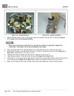
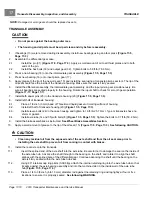
Use a bearing puller or arbor press to remove bearings (16) from the input pinion gear. If the oil seal (10) is
damaged, replace it
See also Figure 17-13, Page 17-8. See following CAUTION.
CAUTION
• Do not reuse bearings after removing them. Replace bearings with new ones.
6.
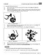
To disassemble the intermediate gear assembly, press off together the bearing (16) and the gear (19)
See also Figure 17-13, Page 17-8.
7.
Press the bearing (18) off the intermediate gear assembly
.
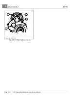
2
1
1. Press Ram
2. Arbor
Figure 17-13
Intermediate Gear Assembly
Page 17-8
2019 Transporter Maintenance and Service Manual
Summary of Contents for TransPorter 4
Page 2: ......
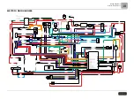
Page 271: ...ELECTRIC MAIN HARNESS Wiring Diagrams Electric Main Harness 18 ...
Page 272: ... Page intentionally left blank ...
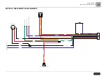
Page 273: ...ELECTRIC INSTRUMENT PANEL HARNESS Wiring Diagrams Electric Instrument Panel Harness 18 ...
Page 274: ... Page intentionally left blank ...
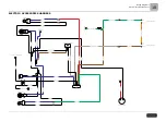
Page 275: ...ELECTRIC ACCESSORIES HARNESS Wiring Diagrams Electric Accessories Harness 18 ...
Page 276: ... Page intentionally left blank ...
Page 282: ...NOTES ...
Page 283: ...NOTES ...
Page 284: ...NOTES ...
Page 285: ......
Page 286: ......

