BRAKE SYSTEM
Brake Adjustment
6
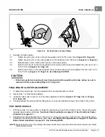
TIPS
2808
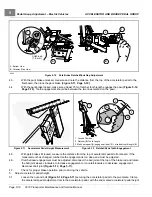
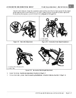
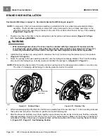
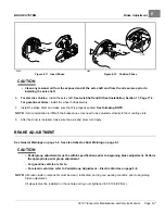
Figure 6-11
Insert Shoes
2800
Figure 6-12
Position Shoes
CAUTION
• Clean any residual oil from the exposed end of the axle shaft and from the oil seal area prior to
installing the axle shaft.
6.
For electric vehicles:
Install the axle shaft.
See Axle Shaft and Oil Seal Installation, Section 17, Page 17-4.
For gasoline vehicles:
Install the wheel hub assembly.
7.
Install the brake drum and make sure that it is properly seated.
See following NOTE.
NOTE:
If drum installation is difficult, the brake shoes may need to be adjusted vertically in the mounting slots.
8.
After the drum is installed, make sure the axle and drum turn freely.
BRAKE ADJUSTMENT
See General Warnings on page 1-2. See also Asbestos Dust Warning on page 6-1.
CAUTION
– Pedal group adjustment must be within specifications prior to beginning brake adjustment. Perform
the appropriate pedal group adjustment.
– For gasoline vehicles, refer to .
– For electric vehicles, refer to Pedal Group Adjustment – Electric Vehicles on page 5-8.
NOTE:
All brake cluster components must be clean, lubricated, and in good working condition prior to beginning
brake adjustment.
All wheels must be installed on the vehicle and lug nuts tightened to 65 ft·lb (88 N·m).
2019 Transporter Maintenance and Service Manual
Page 6-7
Summary of Contents for TransPorter 4
Page 2: ......
Page 271: ...ELECTRIC MAIN HARNESS Wiring Diagrams Electric Main Harness 18 ...
Page 272: ... Page intentionally left blank ...
Page 273: ...ELECTRIC INSTRUMENT PANEL HARNESS Wiring Diagrams Electric Instrument Panel Harness 18 ...
Page 274: ... Page intentionally left blank ...
Page 275: ...ELECTRIC ACCESSORIES HARNESS Wiring Diagrams Electric Accessories Harness 18 ...
Page 276: ... Page intentionally left blank ...
Page 282: ...NOTES ...
Page 283: ...NOTES ...
Page 284: ...NOTES ...
Page 285: ......
Page 286: ......

