6
Emergency Brake System
BRAKE SYSTEM
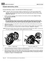
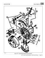
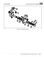
Figure 6-26
Emergency Brake Removal
EMERGENCY BRAKE INSTALLATION
1.
Installation is the reverse of removal.
See also for more info.
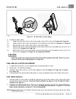
Tighten the emergency brake locknuts (6) to 72
in-lb (8 N·m)
. Tighten the brake lever arm locknuts (2) to 72 in-lb (8 N·m)
.
2.
Safety the cables to the chassis with wire ties.
3.
Adjust the emergency brake.
See Emergency Brake Adjustment on page 6-20.
4.
Perform all brake system inspections.
See Performance Inspection on page 10-1.
EMERGENCY BRAKE ADJUSTMENT
WARNING
• Make sure the brake pedal and park brake function properly before emergency brake adjustment.
CAUTION
• Perform the following procedure only on a level surface. To avoid injury or property damage, ensure
that the path of the vehicle is clear before the vehicle is pushed.
Page 6-20
2019 Transporter Maintenance and Service Manual
Summary of Contents for TransPorter 4
Page 2: ......
Page 271: ...ELECTRIC MAIN HARNESS Wiring Diagrams Electric Main Harness 18 ...
Page 272: ... Page intentionally left blank ...
Page 273: ...ELECTRIC INSTRUMENT PANEL HARNESS Wiring Diagrams Electric Instrument Panel Harness 18 ...
Page 274: ... Page intentionally left blank ...
Page 275: ...ELECTRIC ACCESSORIES HARNESS Wiring Diagrams Electric Accessories Harness 18 ...
Page 276: ... Page intentionally left blank ...
Page 282: ...NOTES ...
Page 283: ...NOTES ...
Page 284: ...NOTES ...
Page 285: ......
Page 286: ......

